
Chromatic dispersion compensation by sub-band

a chromatic dispersion and subband technology, applied in multiplex communication, optical elements, instruments, etc., can solve the problems of increasing the volume of overall packages to an undesirable extent, prohibitive component cost, etc., and achieve cost and package volume savings

Inactive Publication Date: 2006-04-18
CISCO TECH INC
View PDF11 Cites 7 Cited by
  • Summary
  • Abstract
  • Description
  • Claims
  • Application Information

AI Technical Summary

Benefits of technology

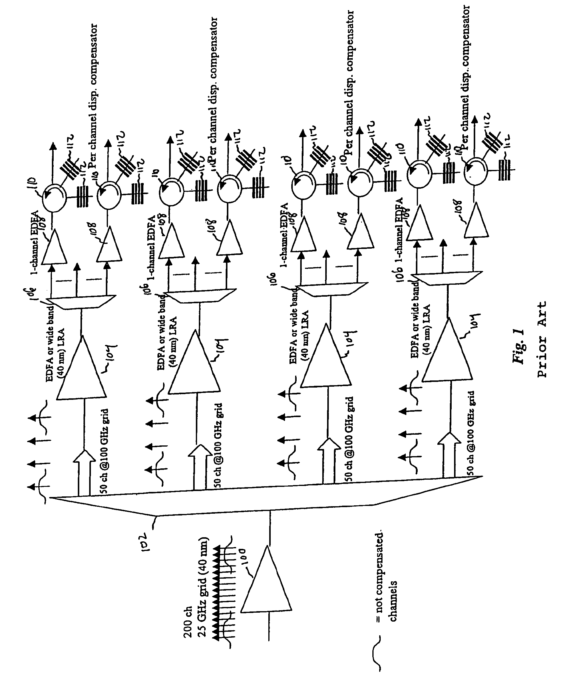
[0009]End of line dispersion compensation is applied on a sub-band by sub-band basis by virtue of one embodiment of the present invention. Adequate end-of-line dispersion compensation may be provided for high data rate WDM systems even for optical link lengths of 1000 km or more. In some embodiments, dispersion compensating gratings (DCGs) are used as the dispersion compensating components. There is a great savings in cost and package volume compared to per-channel compensation schemes.

Problems solved by technology

However, this enormous growth in traffic challenges the telecommunication industry to develop technology that will greatly expand the bandwidth of communication networks.
In particular, with increasing numbers of WDM channels to be compensated, the component cost becomes prohibitive and the overall package volume also increases to an undesirable extent.

Method used


Image

  • Chromatic dispersion compensation by sub-band
  • Chromatic dispersion compensation by sub-band
  • Chromatic dispersion compensation by sub-band

Examples


Embodiment Construction

[0016]One embodiment of the present invention provides an architecture for performing chromatic dispersion compensation on selected sub-bands of a WDM signal. For example, the present invention may be implemented in the context of a WDM receiver at the end of the WDM link where center channels have been adequately chromatic dispersion compensated but channels nearer the grid edges require further compensation. This application is, however, merely representative and the present invention may be implemented wherever applicable.

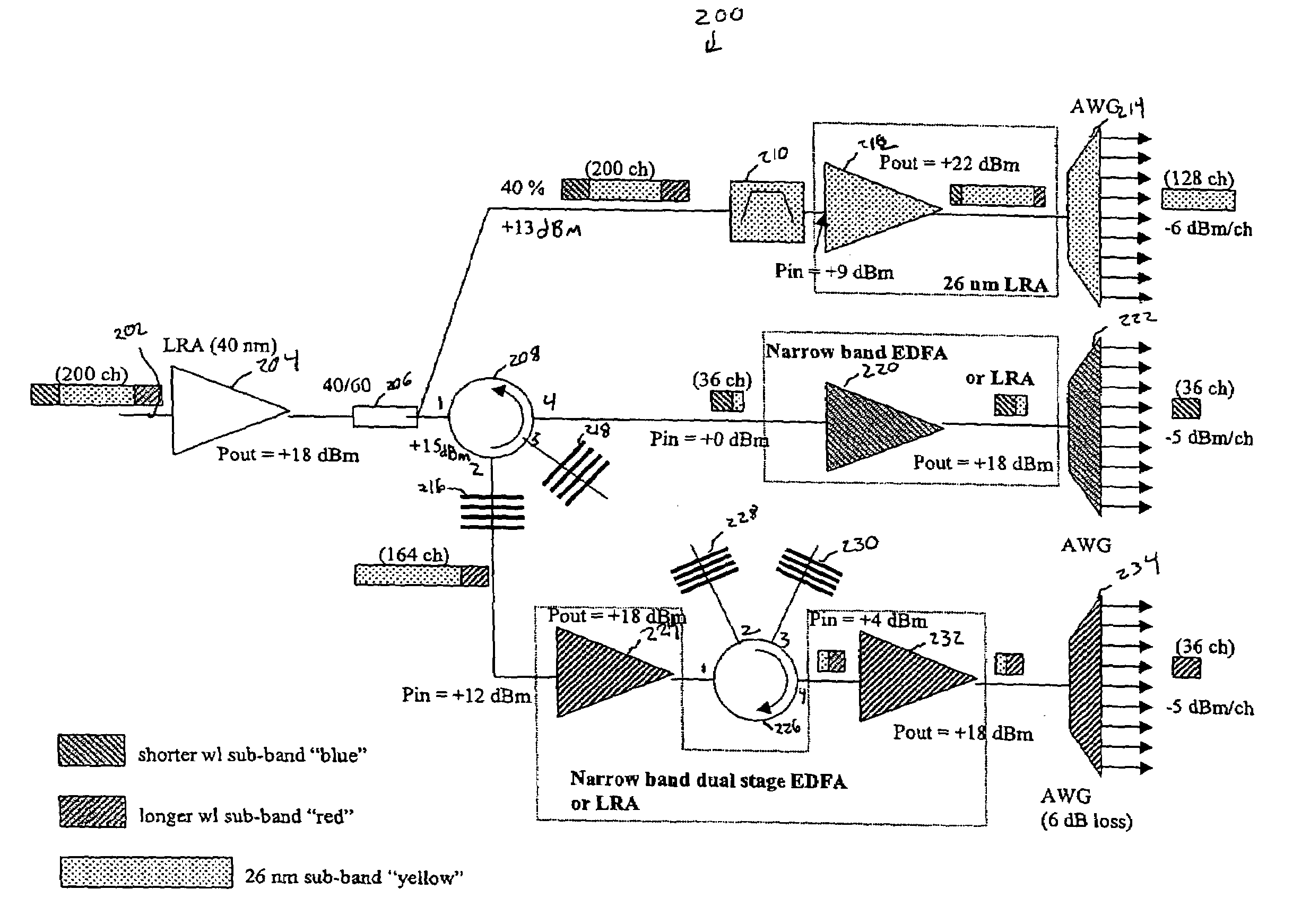
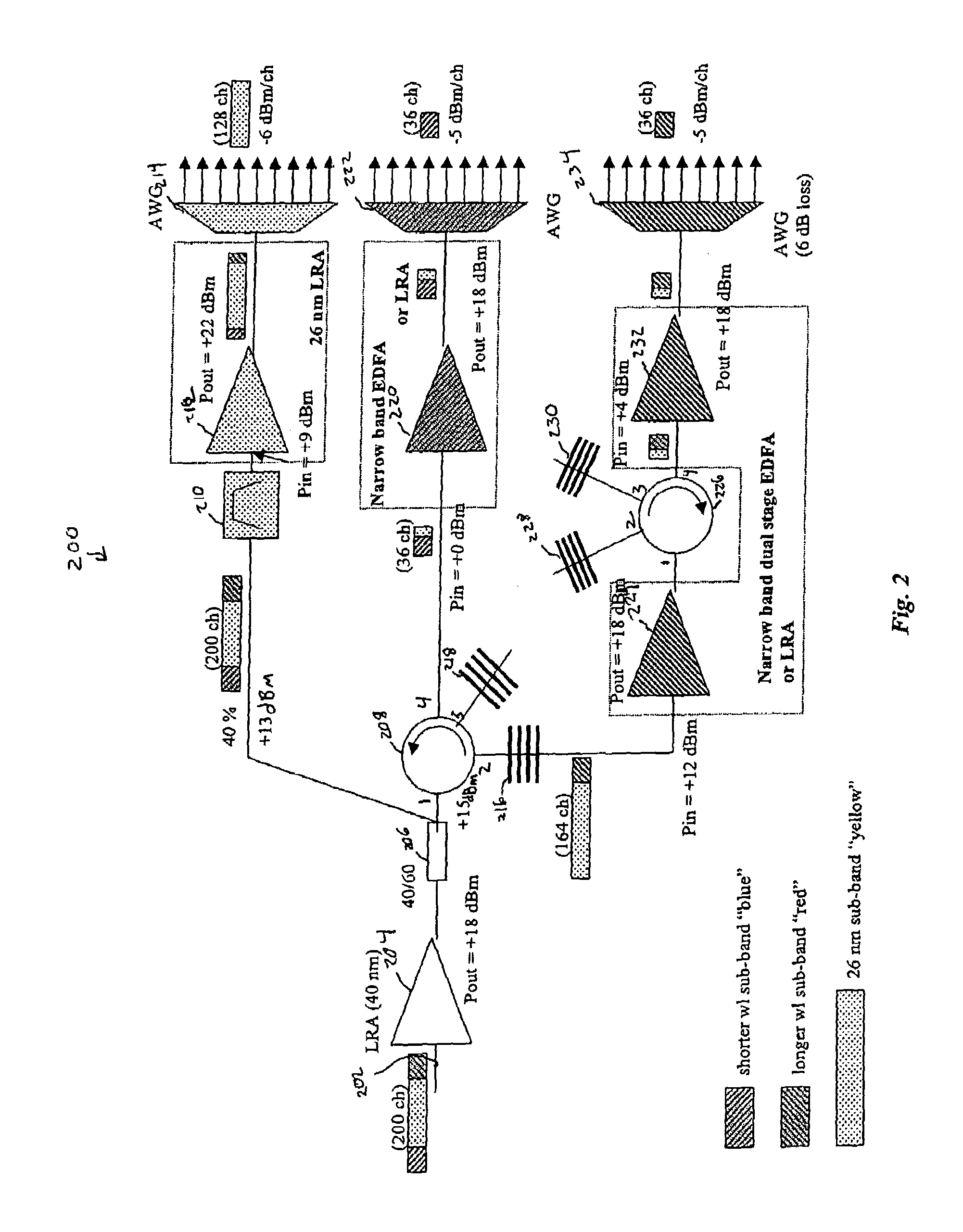
[0017]FIG. 2 depicts a chromatic dispersion compensation system 200 according to one embodiment of the present invention. A received WDM signal 202 is considered to have three sub-bands. Of the 200 channels of WDM signal 202, 128 channels, corresponding to 26 nm of bandwidth, are referred to herein as a “yellow” sub-band. A shorter wavelength sub-band having 36 channels is referred to as the “blue” sub-band and a sub-band having longer wavelength than than the y...


PUM


Abstract

End of line dispersion compensation is applied on a sub-band by sub-band basis. Adequate end-of-line dispersion compensation may be provided for high data rate WDM systems even for optical link lengths of 1000 km or more. Dispersion compensating gratings (DCGs) may be used as the dispersion compensating components. There is a great savings in cost and package volume compared to per-channel compensation schemes.

Description

BACKGROUND OF THE INVENTION[0001]The present invention relates to optical communication systems and more particularly, to systems and methods for compensating for chromatic dispersion in WDM signals.[0002]The explosion of communication services, ranging from video teleconferencing to electronic commerce has spawned a new era of personal and business interactions. As evident in the rapid growth of Internet traffic, consumers and businesses have embraced broadband services, viewing them as a necessity. However, this enormous growth in traffic challenges the telecommunication industry to develop technology that will greatly expand the bandwidth of communication networks. Further improvements in optical communications hold great promise to meet the demand for greater bandwidth.[0003]Wavelength division multiplexing (WDM) technology permits the concurrent transmission of multiple channels over a common optical fiber, thus expanding available bandwidth and providing other advantages in im...

Claims


Application Information

Patent Timeline
IPC IPC(8): H04B10/12
CPCH04B10/25133
Inventor MAZZINI, MARCOCARNIEL, FEDERICO
Owner CISCO TECH INC
Learn More