
Current sense resistor circuit with averaging Kelvin sense features

a resistor circuit and current sense technology, applied in the field of electric circuits, can solve the problems of limiting the working voltage of the system, becoming difficult to define and again becoming difficult to define accurately the actual electrical resistance of rsens

Active Publication Date: 2006-04-18
MICREL
View PDF5 Cites 12 Cited by
  • Summary
  • Abstract
  • Description
  • Claims
  • Application Information

AI Technical Summary

Benefits of technology

"The present invention is about a device called a current sense resistor that has a feature called averaging Kelvin sense. This feature helps to make the device more accurate and reliable. The technical effect of this invention is to improve the accuracy and reliability of current sensing devices."

Problems solved by technology

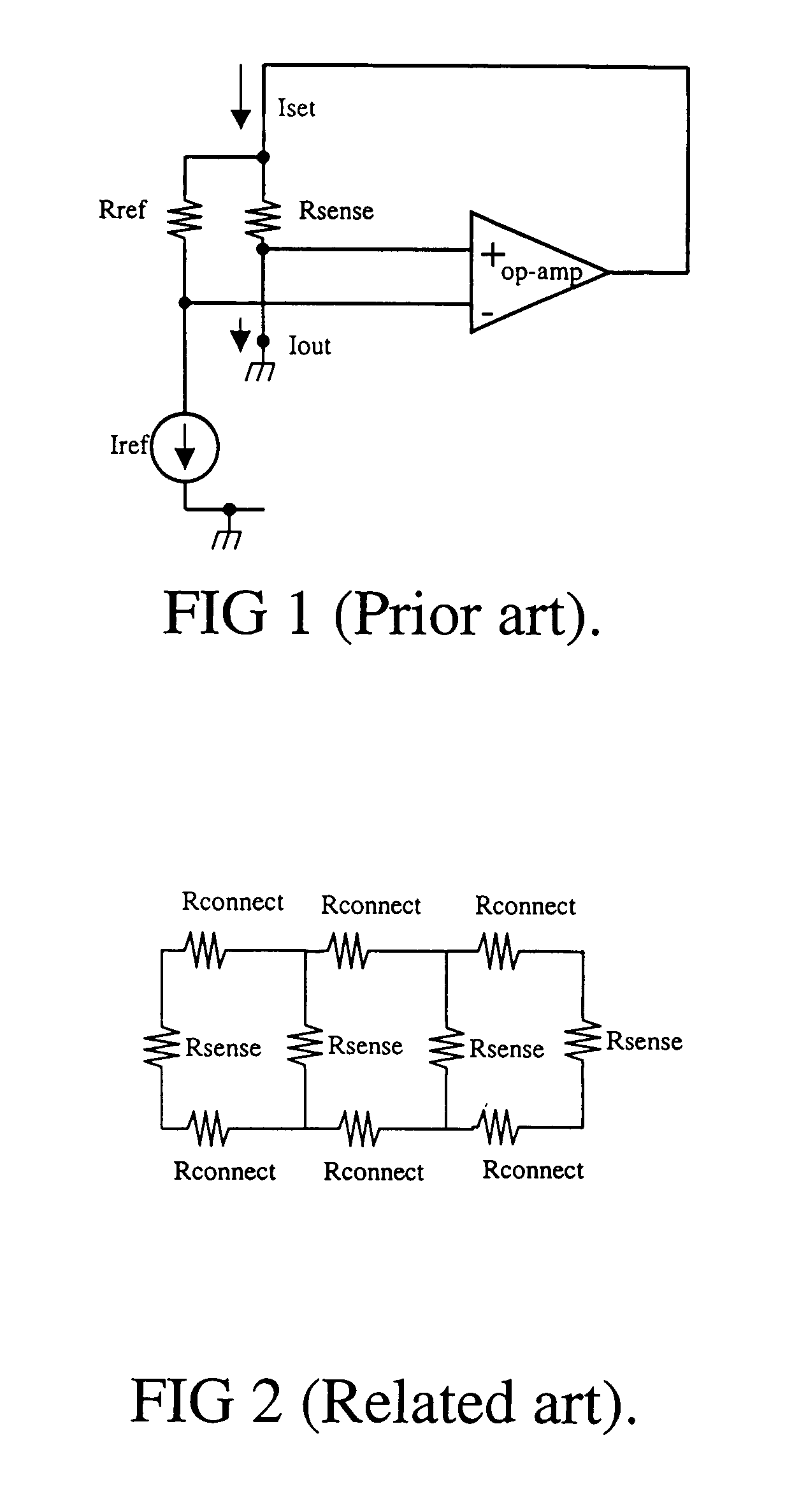
However, for large currents, Iout, the value of Rsense has to be relatively small so as to limit the voltage drop across Rsense; too large a voltage across Rsense often limits the working voltage of the system.
If Rsense is made physically large such as shown in FIG. 2, the metal interconnects, depicted as “Rconnect,” become quite resistive compared to the desired value of Rsense and it becomes difficult to define the actual electrical resistance of Rsense.
If a low resistance material is employed, especially if low compared to interconnect lines to Rsense, the actual electrical resistance of Rsense again becomes difficult to define accurately.
Another complication is that if Rref is made of the same low value resistance material in order to provide accurate matching, Rref then generally needs to be physically large.

Method used


Image

  • Current sense resistor circuit with averaging Kelvin sense features
  • Current sense resistor circuit with averaging Kelvin sense features
  • Current sense resistor circuit with averaging Kelvin sense features

Examples


Embodiment Construction

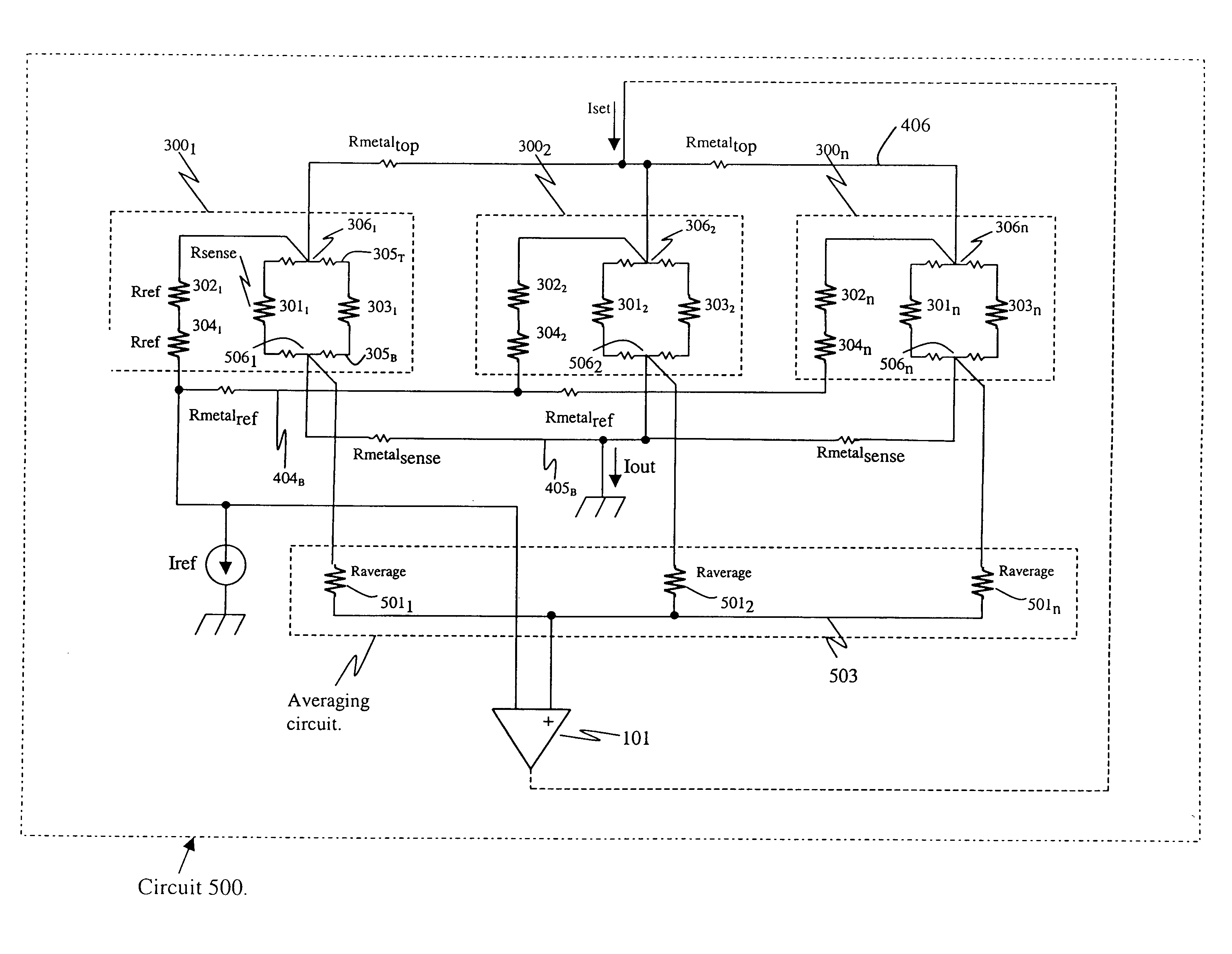
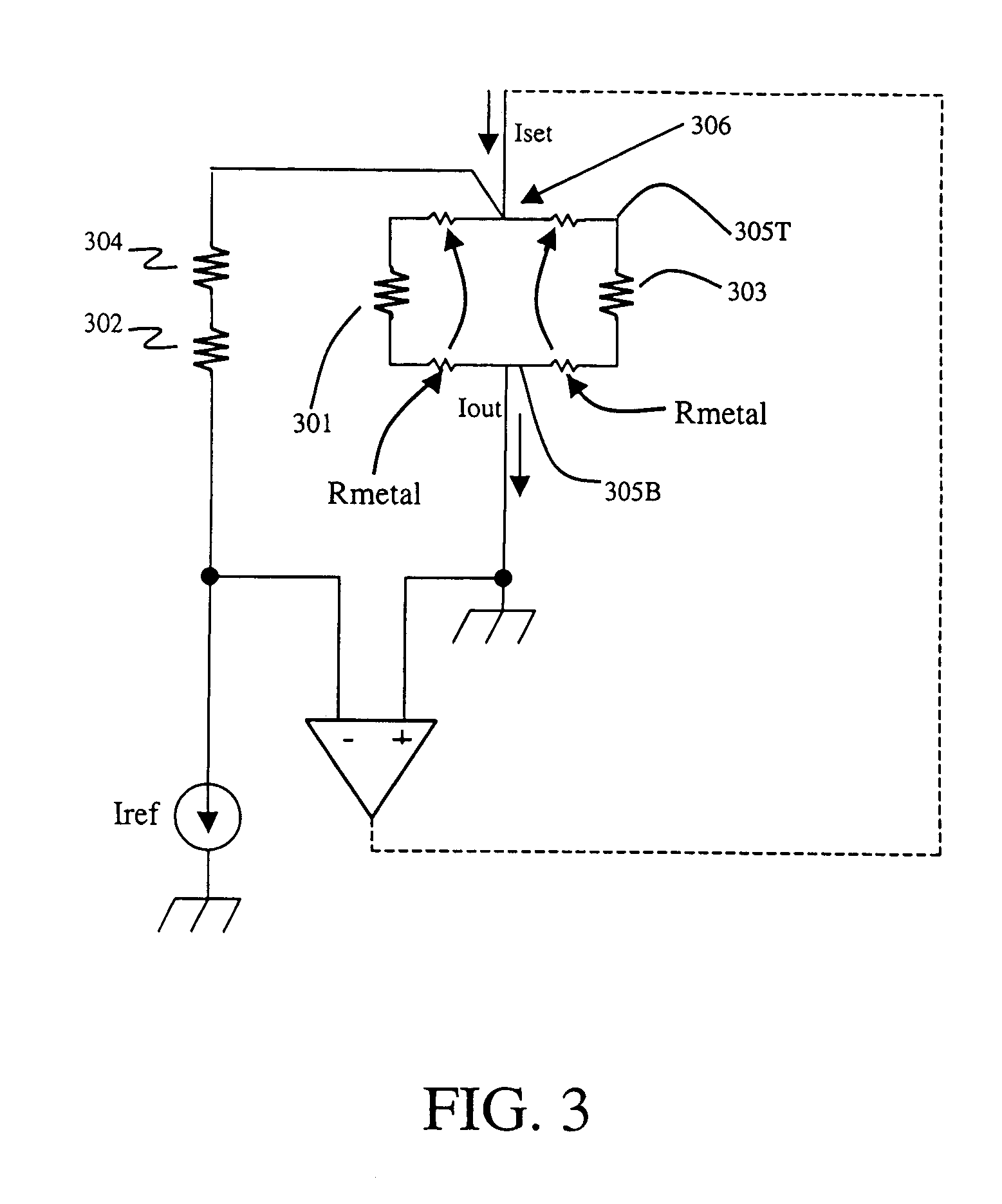
[0020]The present invention provides a method and apparatus for controls using current sensing. The present invention provides for sensing average voltage across a current sense resistor and a reference resistor using a Kelvin connection. Sensing errors due to process gradients in the current sense resistor, temperature changes across the current sense resistor, and the additive affects of interconnect metal resistance are substantially eliminated.

[0021]FIG. 3 is an electrical equivalent circuit diagram for an exemplary embodiment of the present invention. The design is implemented to provide a circuit unit 300 using a plurality of relatively physically small individual sense resistors 301, 303, connected in parallel, such that they may be arranged in close proximity to each other. It is intended by the inventor that the present invention may be implemented in integrated circuit (IC) chips where, as it is well known, it is desirable to pack many elements into microscopic regions of ...


PUM


Abstract

A current sense resistor circuit using Kelvin connection sense features provides an average voltage across net sense resistance and average voltage across net reference resistance to be available at the Kelvin connection points. The Kelvin connections can be used by a negative feedback gain loop to hold the average current through respective reference elements and sense elements substantially constant.

Description

CROSS-REFERENCE TO RELATED APPLICATIONS[0001]Not applicable.STATEMENT REGARDING FEDERALLY SPONSORED RESEARCH OR DEVELOPMENT[0002]Not applicable.REFERENCE TO AN APPENDIX[0003]Not applicable.BACKGROUND[0004]1. Technical Field[0005]The technology described herein is generally related to the field of electrical circuits.[0006]2. Description of Related Art[0007]Electrical current sensing is used in a variety of applications. For example high current demand apparatus, such as motors, generally have control circuits which use current sensing to implement control signals back to the load. FIG. 1 (Prior Art) is an electrical schematic diagram of a conventional current sense circuit 100 for setting a voltage level to a predetermined value for such apparatus operations. For example, and referring to FIG. 1 (Prior Art), measuring a current is accomplished by forcing a current through a first, sense resistor “Rsense” and measuring the voltage “V” across the sense resistor, where VMEASURED=i1·Rse...

Claims


Application Information

Patent Timeline
Patent Type & Authority Patents(United States)
IPC IPC(8): G01R19/00G01R27/00G01R1/04G01R17/10G01R17/12G01R17/18G01R27/08
CPCG01R19/0092G01R1/04
Inventor MOTTOLA, MICHAEL J.
Owner MICREL
Learn More