Lateral projection muzzle brake

a technology of lateral projection and muzzle brake, which is applied in the direction of muzzle attachment, weapon components, weapons, etc., can solve the problems of preventing affecting so as to prevent the proper aiming of the firearm and reduce the recoil for

Inactive Publication Date: 2006-04-25
CRAIG & KERRI CROW LIVING TRUST +1
View PDF14 Cites 61 Cited by
  • Summary
  • Abstract
  • Description
  • Claims
  • Application Information

AI Technical Summary

Benefits of technology

[0010]However, many of the previous muzzle brakes, while alleviating some recoil force upon the firearm, present other problems for the person firing the weapon. First, some of the muzzle brake interfere with the sight line of the weapon, by partially blocking the barrel sight means, thus inhibiting proper aiming of the firearm. Other muzzle brakes deflect the combustion gasses back towards the person firing the weapon, and thus pose risk of powder and gasses being blown back into the eye of the person firing the weapon. Muzzle brakes that deflect the gasses upwards or downwards may cause the end of the barrel of the firearm to be raised or lowered when the gasses are deflected, resulting in problems during repeated firing of the firearm in having to completely re-aim the firearm for subsequent firings of the firearm. In the muzzle brakes previously known, especially those having more than one surface within the muzzle brake to deflect the combustion gasses, none of them provide a graduated deflection of the combustion gasses within the muzzle brake by three reduced diameter bores in the plural surfaces, while having an increasing distance between three brake surfaces along the path of projection, with the gasses deflected equally in opposing lateral directions, helping to maintain the end of the firearm in a level position for repeated firing.
[0011]It is therefore the objectives of the invention to provide a muzzle brake with a flat upper and lower surface to mot impede the sight line of the firearm, to provide the muzzle brake with three brake surfaces of increasing distance from one another subsequent to the end of the rifle barrel, the three brake surfaces having decreasing diameter bores, to provide the three lateral bore to eliminate the combustion gasses equally out both lateral sides of the muzzle brake and not in upward or downward direction, and not in a rearward direction to reduce the risk of the combustion gasses and debris being directed into the eye of the person firing the rifle, the muzzle brake being threaded onto the end of the rifle barrel for application and removal. It is also the objective of the present muzzle brake to provide the device in one singular component without any moving or assembled components for simplicity of manufacture, cleaning and maintenance.

Problems solved by technology

However, many of the previous muzzle brakes, while alleviating some recoil force upon the firearm, present other problems for the person firing the weapon.
First, some of the muzzle brake interfere with the sight line of the weapon, by partially blocking the barrel sight means, thus inhibiting proper aiming of the firearm.
Other muzzle brakes deflect the combustion gasses back towards the person firing the weapon, and thus pose risk of powder and gasses being blown back into the eye of the person firing the weapon.
Muzzle brakes that deflect the gasses upwards or downwards may cause the end of the barrel of the firearm to be raised or lowered when the gasses are deflected, resulting in problems during repeated firing of the firearm in having to completely re-aim the firearm for subsequent firings of the firearm.

Method used


Image

  • Lateral projection muzzle brake
  • Lateral projection muzzle brake
  • Lateral projection muzzle brake

Examples


Embodiment Construction

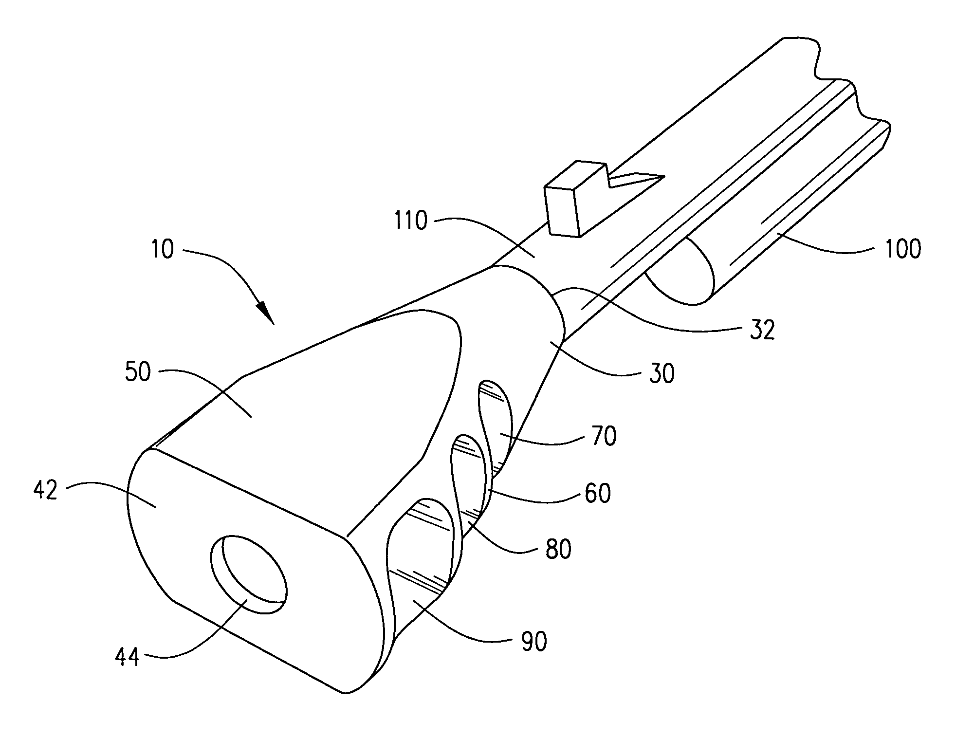
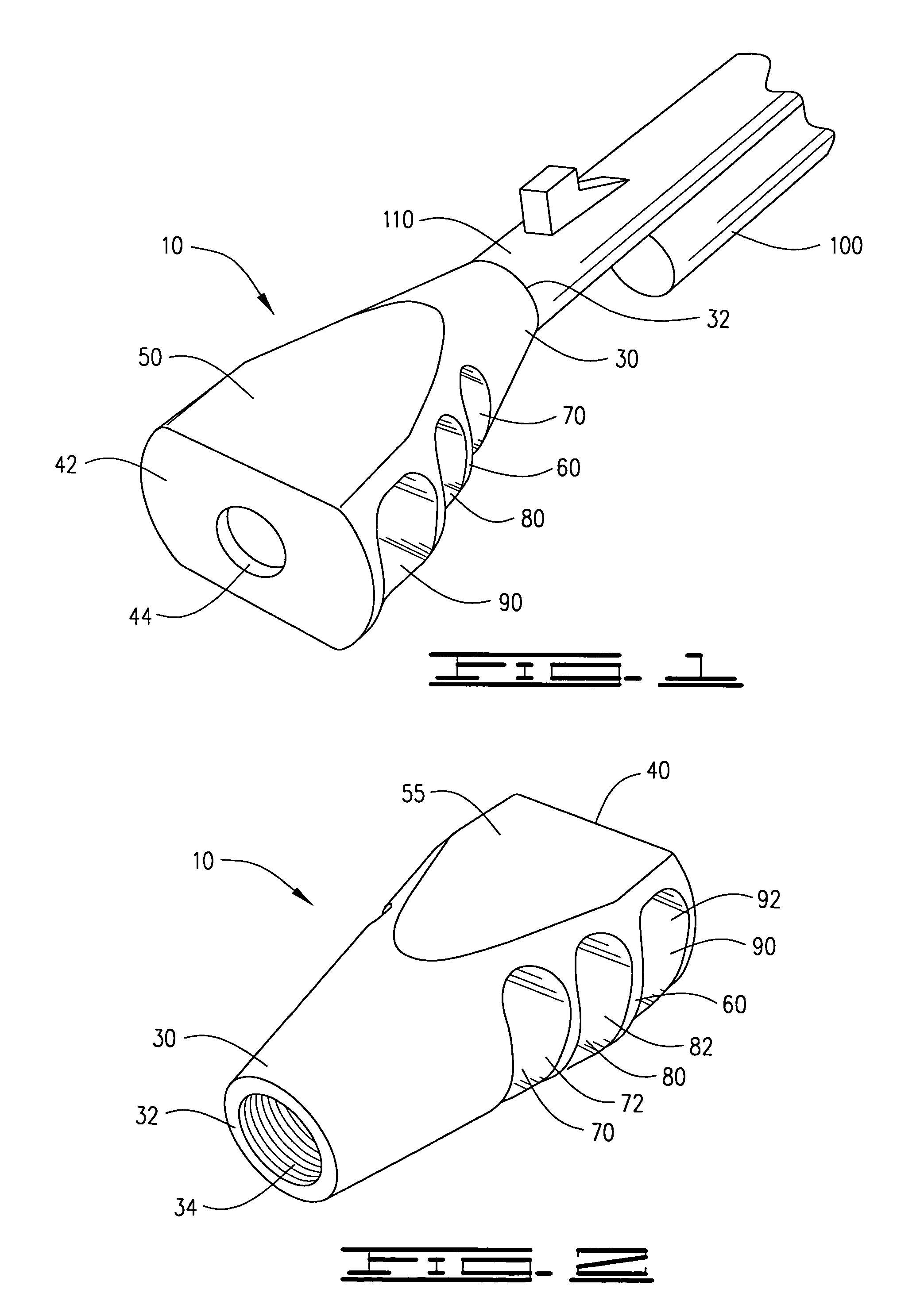
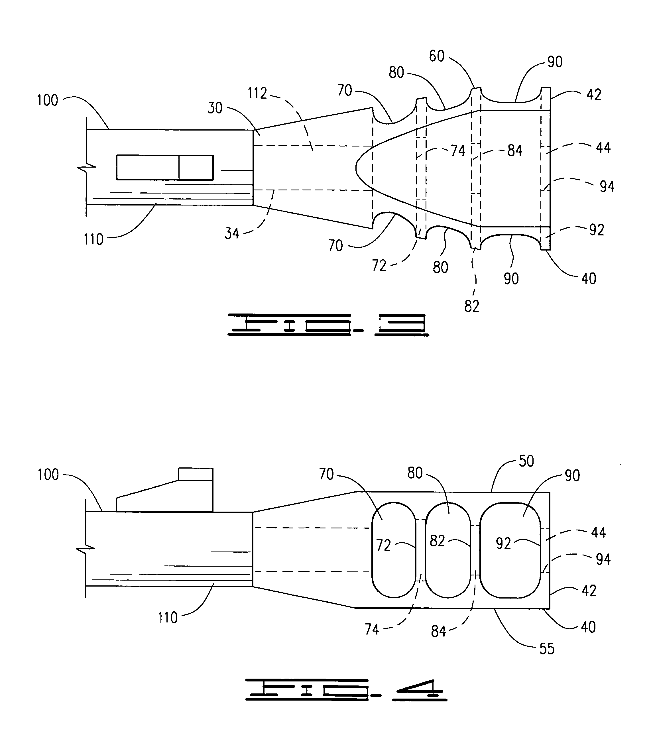
[0020]An improved muzzle brake 10 for application to the end 112 of a barrel 110 of a firearm 100, to provide a forward force to counteract the recoil force of the firearm 100 during firing, shown in FIGS. 1–7 of the drawings, comprises a tapered body 20 having a narrowed first end 30 including an attachment opening 32 having internal machine threads 34 adapted to engage external machine threads on the end 112 of the barrel 110 of the firearm 100, an expanded second end 40, having a flattened outer surface 42 with a central projectile bore 44, a flat upper surface 50 which does not impede the line of sight of the firearm 100 and a flat lower surface 55, the body 20 further providing two lateral sides 60 through which are provided a first lateral oval vent 70 defining a first flat brake plate 72 having a first central bore 74, a second lateral oval vent 80 defining a second flat brake plate 82 having a second central bore 84 and a third lateral oval vent 90 defining a third flat brak...


PUM


Abstract

An improved muzzle brake, attached to the end of a rifle barrel reducing the recoil of the rifle includes an internally threaded attaching end, engaging outer threads of a rifle barrel, a flattened projectile end, with an overall increasing taper from the attaching end to the projectile end, a flat upper surface which does not impede the sight line of the rifle, a flat lower surface, and two lateral surfaces including a first lateral oval vent, a second lateral oval vent and a third lateral oval vent, the first lateral vent defining a first flat brake plate having a first central bore, the second lateral oval vent defining a second flat brake plate having a second central bore and the third lateral oval vent defining a third flat brake plate having a third central bore penetrating through the projectile end, wherein a bullet fired from the rifle travels through the attaching end, the first central bore, second central bore and third central bore, while the gasses generated by the fired projectile are deflected laterally by the first flat brake plate, second flat brake plate and third flat brake plate, forcing the rifle forward, reducing the recoil force of the fired rifle.

Description

CROSS REFERENCE TO RELATED APPLICATIONS[0001]NoneI. BACKGROUND OF THE INVENTION[0002]1. Field of Invention[0003]An improved muzzle brake, attached to the end of a rifle barrel reducing the recoil of the rifle includes an internally threaded attaching end, engaging outer threads of a rifle barrel, a flattened projectile end, with an overall increasing taper from the attaching end to the projectile end, a flat upper surface which does not impede the sight line of the rifle, a flat lower surface, and two lateral surfaces including a first lateral oval vent, a second lateral oval vent and a third lateral oval vent, the first lateral vent defining a first flat brake plate having a first central bore, the second lateral oval vent defining a second flat brake plate having a second central bore and the third lateral oval vent defining a third flat brake plate having a third central bore penetrating through the projectile end, wherein a bullet fired from the rifle travels through the attachi...

Claims


Application Information

Patent Timeline
Patent Type & Authority Patents(United States)
IPC IPC(8): F41A21/00
CPCF41A21/36
Inventor BOUNDS, ROGER
Owner CRAIG & KERRI CROW LIVING TRUST
Why Eureka
Try Eureka