Liquid leak detector and automatic shutoff system

a liquid leak detector and automatic shutoff technology, applied in the direction of fluid-tightness measurement, instrumentation, fluid loss/gain rate measurement, etc., can solve the problems of linoleum floors, carpet, hardwood floors, linoleum floors, etc., and achieve the effect of greater energy efficiency

Inactive Publication Date: 2006-04-25
HASSENFLUG BRIAN EDWARD
View PDF13 Cites 106 Cited by
  • Summary
  • Abstract
  • Description
  • Claims
  • Application Information

AI Technical Summary

Benefits of technology

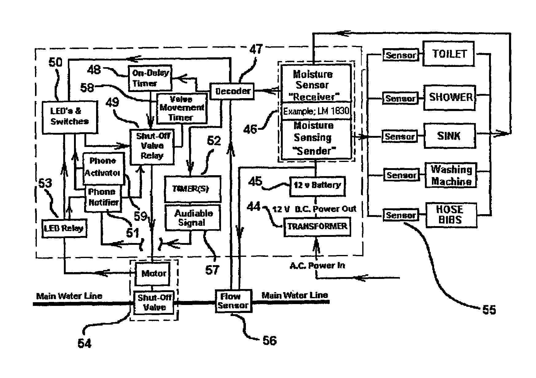
[0021]The present invention addresses the aforementioned problems by providing a conductive fluid flow supply system that minimizes conductive fluid leakage whenever a leak is detected in a fluid line. In its broadest sense, the object of the present invention is to provides a method for controlling forward conductive fluid flow between a first point (example; water flow sensor out side the home or building) and a second point (water sensors placed in or at the ends of the water dependent appliances) of a pressurized conductive fluid line. The method includes detecting conductive forward fluid flow at the first point and continuing to allow the forward fluids flow to the second point(s), when conductive forward fluid flow at the second point(s) are also detected. (ie; allowing the main water line shut off valve to remain in its “Open” position) The method further includes preventing conductive forward fluid flow (by way of shutting off the main water line valve) at the first point if conductive forward fluid flow is detected at the first point and not detected at the second point(s).
[0025]The circuitry of this invention will be referred to from this point on as the brain(s) of the system. The brain(s) will be placed in a control panel in an easily accessible location in the building. The visible control panel comprises of a panel that will house some or all of the circuitry that runs the system as well as indicating LED's, manual valve open-close, reset button, an all power off button, an automation system off / on button, an numerical keypad, a user number set button, an timer reset button, an digital display panel, and a audible alarm. The LED's are designed to help notify the user of the current system status.
[0029]The automation system on / off button could allow the user to shut down just the automated portion of the system. This is to allow for the filling of a new water heater or to bleed the fluid lines of air without a premature automated shutdown of the water flow.
[0036]If the user wishes to do repairs or maintenance in the building that requires the water to be shut off, or just wishes to turn the water off while away on an extended vacation, the manual on-off button may be used to turn the main water shut off valve to the off position eliminating the flow of water to the building. This causes a solid red light to be displayed in place of the solid green light.
[0046]1. My electrically actuated valve requires no power source to maintain its open or closed position, as opposed to a solenoid actuated valve which returns to its original position during a loss of power. This results in far greater energy efficiency as well as maintaining the desired open or closed position during an interruption of power.2. The battery back up allowing for continual system monitoring even in the event of a loss of electrical power.3. Does not rely on pressure switches, timing fluid usage, floor based moisture sensors, or the counting of gallons to operate.4. Has hard wired and wireless moisture sensing options.5. Automatically closes and opens valve(s) at predetermined intervals to maintain freedom of valve movement.6. Has a control panel to view and operate the system with a touch of a button(s).7. Monitors the entire fluid system from line entry to all desired fluid exit points.8. Contacts the user (when the user is away) by way of telephonic communication of a automatic shut down of the main water supply valve due to a water leak detected, without a monthly security company charge.9. Contacts the user (when the user is away) by way of telephonic communication of excessive water usage, without a monthly security company charge.10. The option of shutting off the main water shut off valve by way of telephonic communication.11. A warning audible signal of excessive water usage.12. A warning beeping audible signal of an automatic water supply shut down, due to a leak.13. The ability to connect numerous systems together, to monitor an entire apartment complex, by either building by building, or each and every apartment individually.14. And controls leaks in broken frozen pipes, with out the requirements of additional equipment.

Problems solved by technology

The damage caused by water leaking from a broken water line in a house or building can be extensive and typically exceeds several thousand dollars per household.
Water destroys carpet, drywall, hardwood floors, linoleum floors, etc. and can even cause floor foundation to warp.
Water leaking into a home or building also can cause mold to grow in and around your walls and floors.
Some of these molds have been known to cause serious medical problems and on rare occasions even death, for those who are exposed to it for an extended period of time.
The seriousness of this problem is evidenced by the large volume of patents filed in the US alone.
These systems are only effective if the leak occurs at the exact location that the water sensor is located.
If there were a leak in a cooper line where a fitting became weak and started to leak, these systems would not detect this leak until the (undesired) water level in the house reaches one or more of these sensors for it to shut down the main water supply to the building.
Another example would be if the Building user was to need to clean the floor surface with a liquid cleaning solution, and the liquid cleaning solution, (for example water and bleach or ammonia) was to come into contact with one of the sensors placed on the floor surface around the water dependent appliance, then the sensor would again ultimately send a signal to prematurely terminate the main water supply to the building, not only prematurely terminating the water supply to the building, but also misleading the Building user that there was a water leak when there was not.
If the building users were present and entering in and out of locations where these motion sensors were located in the building, and there was a leak in a water supply line in a location anywhere in the home or building.
The system cannot be used during periods of normal water usage since the water flow which results, for example, when a simple faucet is turned on would activate the system and thereby shut off the supply of water.
Accordingly, this system is only realistically useable when the home owner intends to be away from home for an extended period of time or does not expect to use the system, for example at night.
However, use of the system at night is not realistic either since most homeowners use bathroom facilities at night.
U.S. Pat. No. 5,029,605 point out that deposits that accumulate in pipes and valves over a period of time may impede the actuation of solenoid-type valves.
If the pressure drops in the system for any reason while the water in not in use, (ie dripping faucet, shower head, running toilet due to a bad flap, etc. . . . ) then when water is requested from a water dependent appliance, the pressure in the water pipes will not be enough to trigger the flow sensor in order to ultimately turn the main water valve “on” and receive water to the water dependent appliance that was requesting it.
A few examples of this are that, the pressure could have dropped due to a faucet drip, shower drip, or etc. . . . Power could have been interrupted to the main water valve, thus making it impossible for it to open, or there could actually be a small or large water leak in the pipe.
This would open and close the main water valve at least dozens of times a day, every day 365 days a year, which would not only consume excessive power, but would also deteriorate the life expectancy of the main water valve, and circuitry tremendously.
Unfortunately, if you decide to shower, water the grass or plants, wash the car, longer than usual, then this system could automatically shut the supply of water off to the house or building prematurely.

Method used


Image

  • Liquid leak detector and automatic shutoff system
  • Liquid leak detector and automatic shutoff system
  • Liquid leak detector and automatic shutoff system

Examples


example 1

[0057]Thereby passing through the faucet's inlet 32A, as shown in FIG. 4 and on through to the faucet's outlet 32B, and through the isolating adapter 33, which holds the aerator, and isolates the main water supply line from the corrosive resistant, conductive connecting washer 34, which is designed to slide over the isolator 33, having an AC signal attached to it, and to remain in place, and the corrosive resistant conductive end cap 35 which is designed to be removed and replaced, by way of threaded connection to the isolator 33 without disconnecting the AC signal that is connected to corrosive resistant conductive connecting washer 34, because the corrosive resistant conductive end cap 35 holds the clean out screen for easy screen clean out. When screwed on tightly, it makes contact with the corrosive resistant, conductive connecting washer 34, also making the corrosive resistant, conductive end cap 35 connected to the AC signal. It also incorporates a cross sectional member 35 fo...


PUM


Abstract

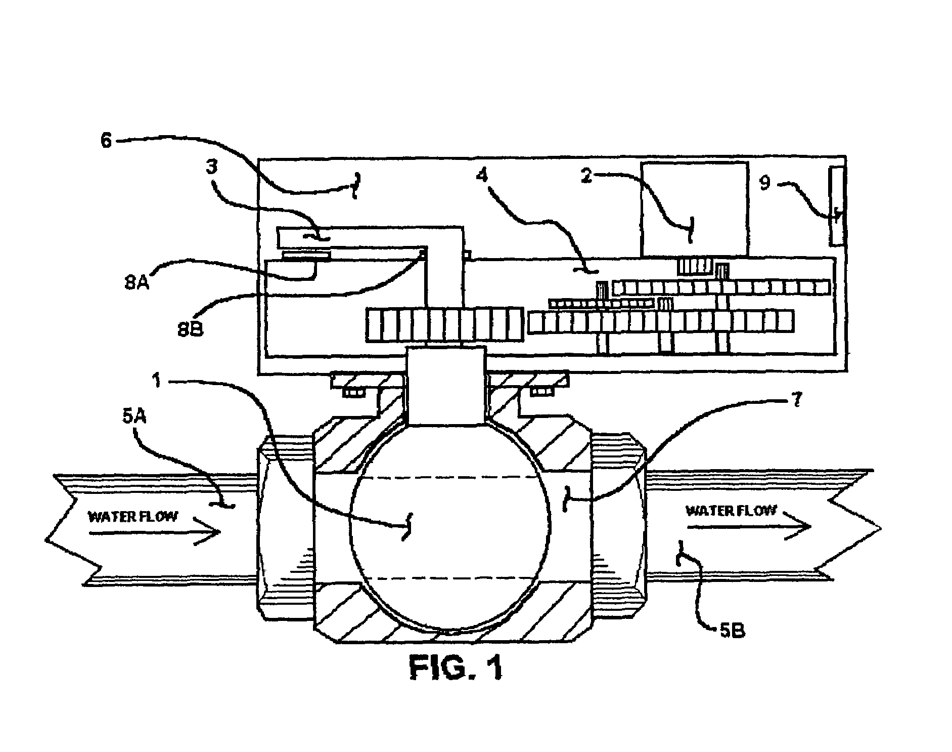
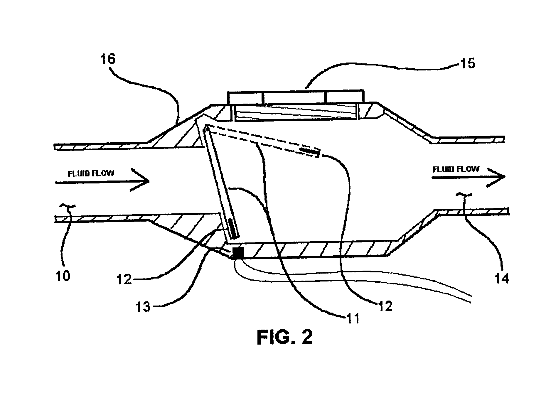
A flapper is provided in the main conductive fluid supply inlet line, and a permanent magnet is affixed to the bottom of the flapper. Adjacent to the flapper, outside the pipe, a magnetically operated switch is placed. Conductive fluid sensors are placed in or on conductive fluid dependent appliances, to determine the presence or absence of flowing conductive fluids. The flapper's switch and the conductive fluid sensors are connected in circuit with a relay, which in turn controls an electrically actuated valve cutting off or permitting the entry of fluids from the source to the inlet pipe. If the switch is activated, and one or more of the fluid sensors is not, within a predetermined time period, then the electrically actuated valve will cut off the entry of fluids from the source to the inlet pipe. If the switch and sensors are activated concurrently, normal fluid flow will be permitted.

Description

[0001]This application claims the benefit of Provisional Application No. 60 / 327,829, filed Oct. 9, 2001.BACKGROUND OF INVENTION[0002]1. Field of Invention[0003]The Invention is generally directed to fluid flow control systems and, more particularly, to a system for preventing unwanted conductive fluid flow, particularly water flow, when ever a break in a conductive fluid line occurs.[0004]2. Description of Related and Prior Art[0005]The damage caused by water leaking from a broken water line in a house or building can be extensive and typically exceeds several thousand dollars per household. Water destroys carpet, drywall, hardwood floors, linoleum floors, etc. and can even cause floor foundation to warp. Water leaking into a home or building also can cause mold to grow in and around your walls and floors. Some of these molds have been known to cause serious medical problems and on rare occasions even death, for those who are exposed to it for an extended period of time. While the p...

Claims


Application Information

Patent Timeline
Patent Type & Authority Patents(United States)
IPC IPC(8): G01M3/26G01F1/28G01M3/04G01M3/18G01P13/00
CPCG01F1/28G01P13/0033G01M3/184G01M3/045
Inventor HASSENFLUG, BRIAN EDWARD
Owner HASSENFLUG BRIAN EDWARD
Why Eureka
Try Eureka