Device for supporting a material web

a technology of supporting device and material web, which is applied in the direction of conveyors, stock shearing machines, sawing apparatus, etc., can solve the problems of tight holding paper, which has a tendency to sag, and achieve the effect of improving edge retention

Inactive Publication Date: 2006-04-25
WILL-PEMCO
View PDF19 Cites 1 Cited by
  • Summary
  • Abstract
  • Description
  • Claims
  • Application Information

AI Technical Summary

Benefits of technology

[0007]Thus, it is an object of the present invention to support the conveyed paper webs on the longitudinal cutting device and to improve the edge retention at the longitudinal cutting blades.

Problems solved by technology

The tightly held paper, however, has a tendency to sag in those locations where it is not supported by the lower blades, meaning between the rollers and / or the longitudinal cutting blades.

Method used


Image

  • Device for supporting a material web
  • Device for supporting a material web
  • Device for supporting a material web

Examples


Embodiment Construction

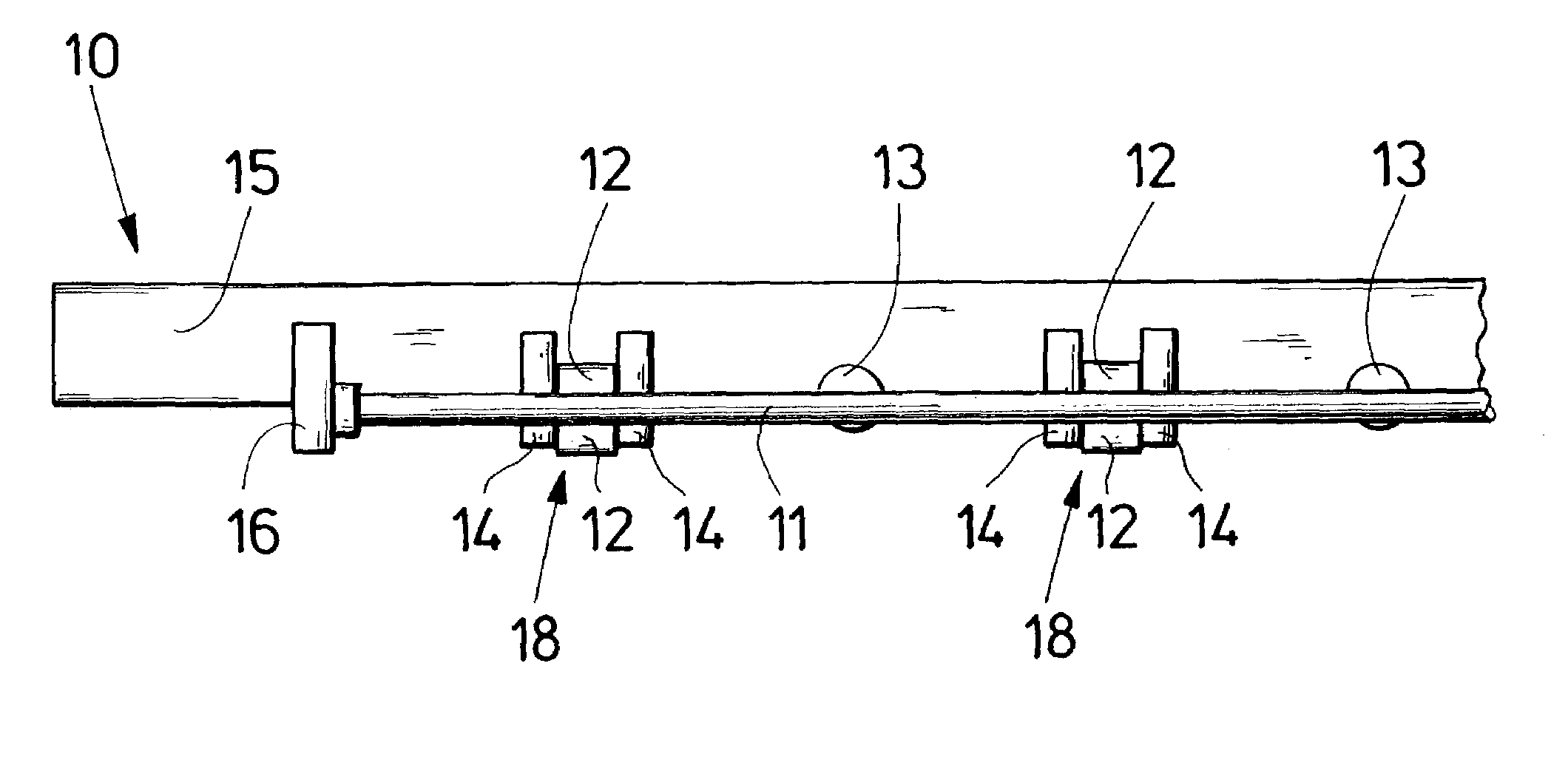
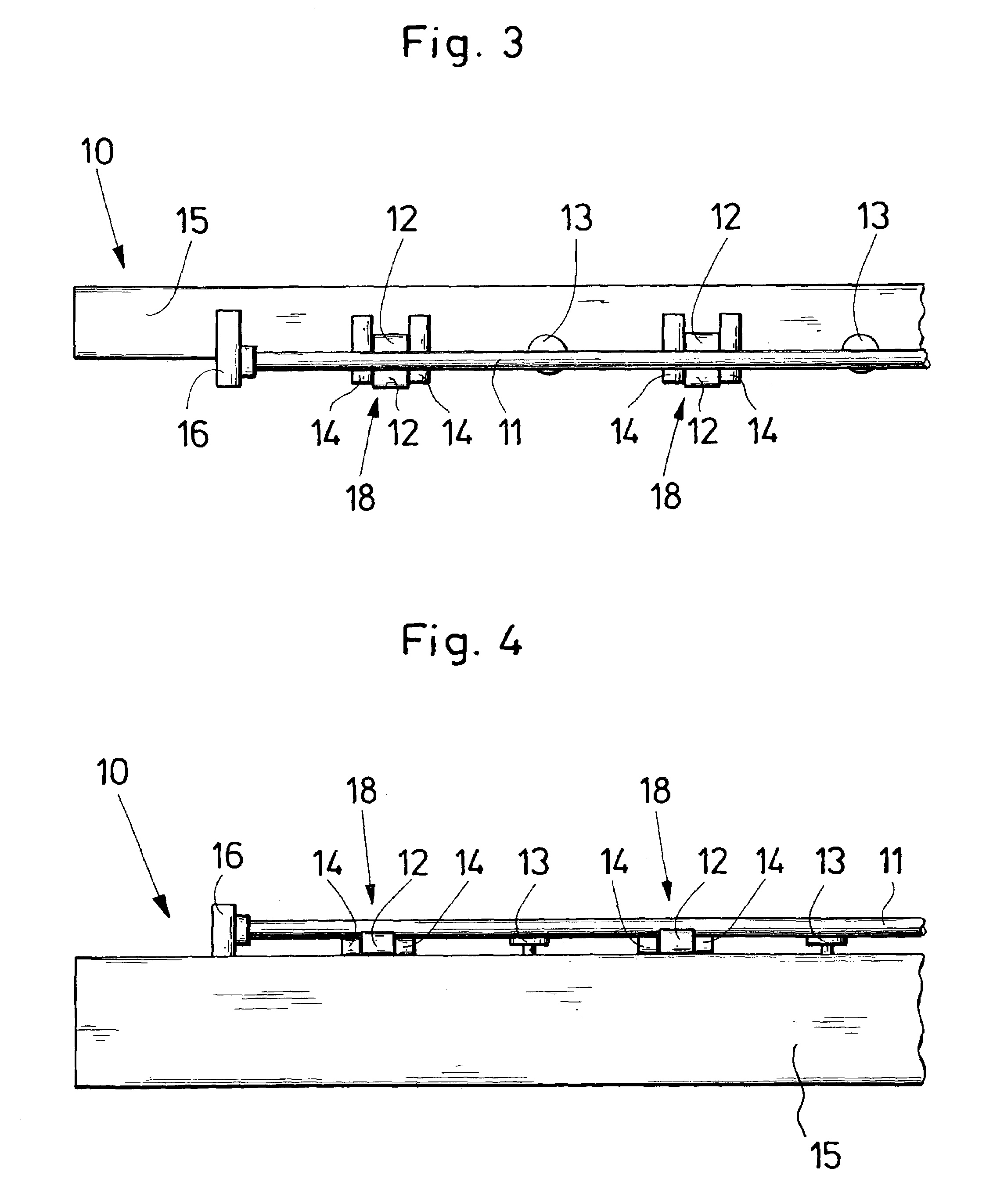
[0034]In the Figures described herein, the same elements are given the same reference numbers and will not introduced anew in each case.

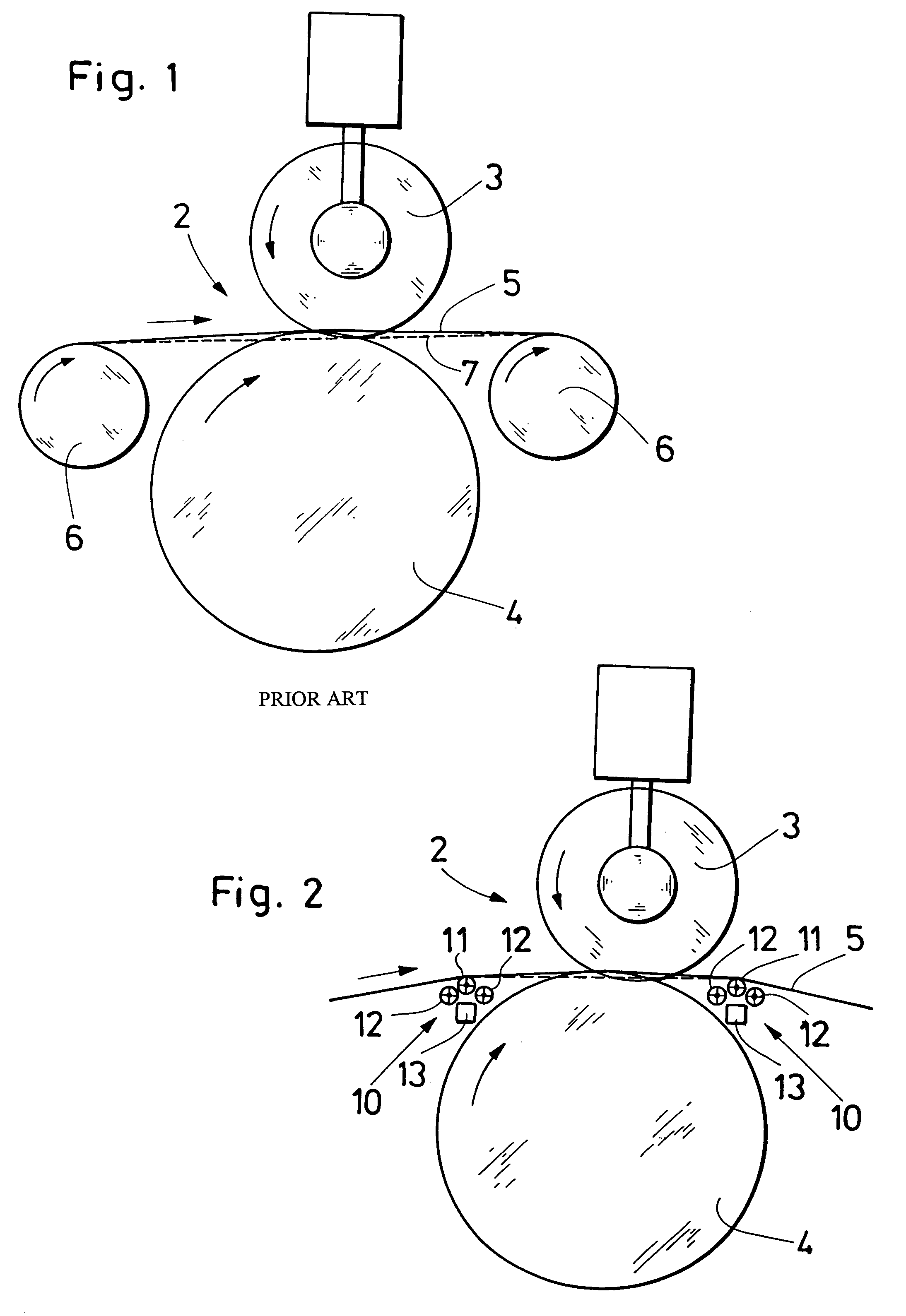
[0035]FIG. 1 shows an arrangement for cutting a paper web 5 in a longitudinal cutting station of a paper-processing machine. The longitudinal cutting station comprises a longitudinal cutting device 2 with an upper knife 3 and a lower knife 4, which make a tangential cut through the paper web that moves between the lower knife and the upper knife.

[0036]Respectively one support shaft 6 is arranged in front of the longitudinal cutting device 2 and behind the longitudinal cutting device 2 to support the paper web 5 in transverse direction, meaning in a plane that is perpendicular to the drawing plane. Owing to the width of the paper web 5, it is necessary for the support shafts 6 to have sufficient stability across the complete width of the paper web. For this, the support shafts 6 are designed to have a correspondingly large diameter of up to 150 mm. B...


PUM

PropertyMeasurementUnit
diameteraaaaaaaaaa
axis of rotationaaaaaaaaaa
distancesaaaaaaaaaa

Abstract

A support for a material web for use with a longitudinal cutting device for cutting the material web, includes a support shaft having an axis of rotation. At least one bearing mechanism positions the at least one support shaft, wherein the at least one bearing mechanism has an axis of rotation outside of the axis of rotation of the support shaft.

Description

CROSS-REFERENCE TO RELATED APPLICATION[0001]This application claims the priority of German Patent Application No. 102 06 323.0 filed Feb. 14, 2002, the disclosure of which, together with the disclosure of each U.S. and foreign patent and patent application mentioned below, is incorporated herein by reference.BACKGROUND OF THE INVENTION[0002]The invention relates to a support for a material web, especially a paper web, on a cutting device for the material web, in particular a longitudinal cutting device on a machine in the paper-processing industry. The invention furthermore relates to the use of a support of this type, to an arrangement for cutting a material web, especially a paper web, and to a machine in the paper-processing industry.[0003]A format cutter manufactured by the assignee of the present application and marketed under the designation SLK is already known. For this cutter, several paper webs are joined in front of a longitudinal cutting device and are then cut into stri...

Claims


Application Information

Patent Timeline
Patent Type & Authority Patents(United States)
IPC IPC(8): B26D7/06B26D1/24B65H23/26B65H35/02
CPCB65H23/26B65H35/02B65H2301/4148Y10T83/664Y10T83/7809Y10T83/6584Y10T83/4702Y10T83/727Y10T83/2196Y10T83/4838
Inventor HOPNER, BERNDHITSCHER, THOMAS
Owner WILL-PEMCO
Why Eureka
Try Eureka