
Stud for a tyre

a technology for studs and tyres, which is applied in the direction of tyre tread bands/patterns, special tyres, non-skid devices, etc., can solve the problems of poor resistance of studs with steel bodies, easy to fall off hard metal peak, and damage to internal ply, etc., to achieve the effect of reducing weight, reducing wear, and reducing wear

Inactive Publication Date: 2006-04-25
TURVANASTA
View PDF13 Cites 15 Cited by
  • Summary
  • Abstract
  • Description
  • Claims
  • Application Information

AI Technical Summary

Benefits of technology

[0008]The invention provides a very lightweight stud with adequate durability characteristics. The weight of the stud may be even less than half of the weight of a steel stud of equal size. The stud causes less wear to the road surface. The stud is more silent, since it has lighter weight. The flexible locking flange is substantially retained in position despite the tilting of the stud. Since the actual appearance and dimensions of the stud do not differ from those of conventional steel studs, the studs can be fixed in the tyres using existing operational equipment. Given the small size of the metal body portion, there will be very low waste percentage of raw material if the manufacture is carried out using turning. In addition, the plastic part has proved to withstand abrasion against rubber better than a steel stud, and consequently the stud is better retained in the tyre.

Problems solved by technology

As a result of this, again, the edge of the stud-locking flange has entailed such heavy wear of the tyre rubber under the tilting movements of the stud that the internal ply has been damaged and even the tyre punctured.
Plastic and aluminium studs are known, but they have poorer resistance than studs with a steel body.
Gravel and asphalt dust cause very rapid wear of the plastic or aluminium body surrounding the hard metal peak, so that the hard metal peak may easily come off.
This type of stud involves the problem of the metal stud body being strongly tapered towards the stud flange portion.
In this stud model, the shank portion is clearly narrower than the bottom portion, so that the same apparatus intended for mounting conventional studs cannot be used for mounting this stud.
This results in low friction between the stud and the tyre, so that the stud may be detached from the tyre.

Method used


Image

  • Stud for a tyre
  • Stud for a tyre

Examples


Embodiment Construction

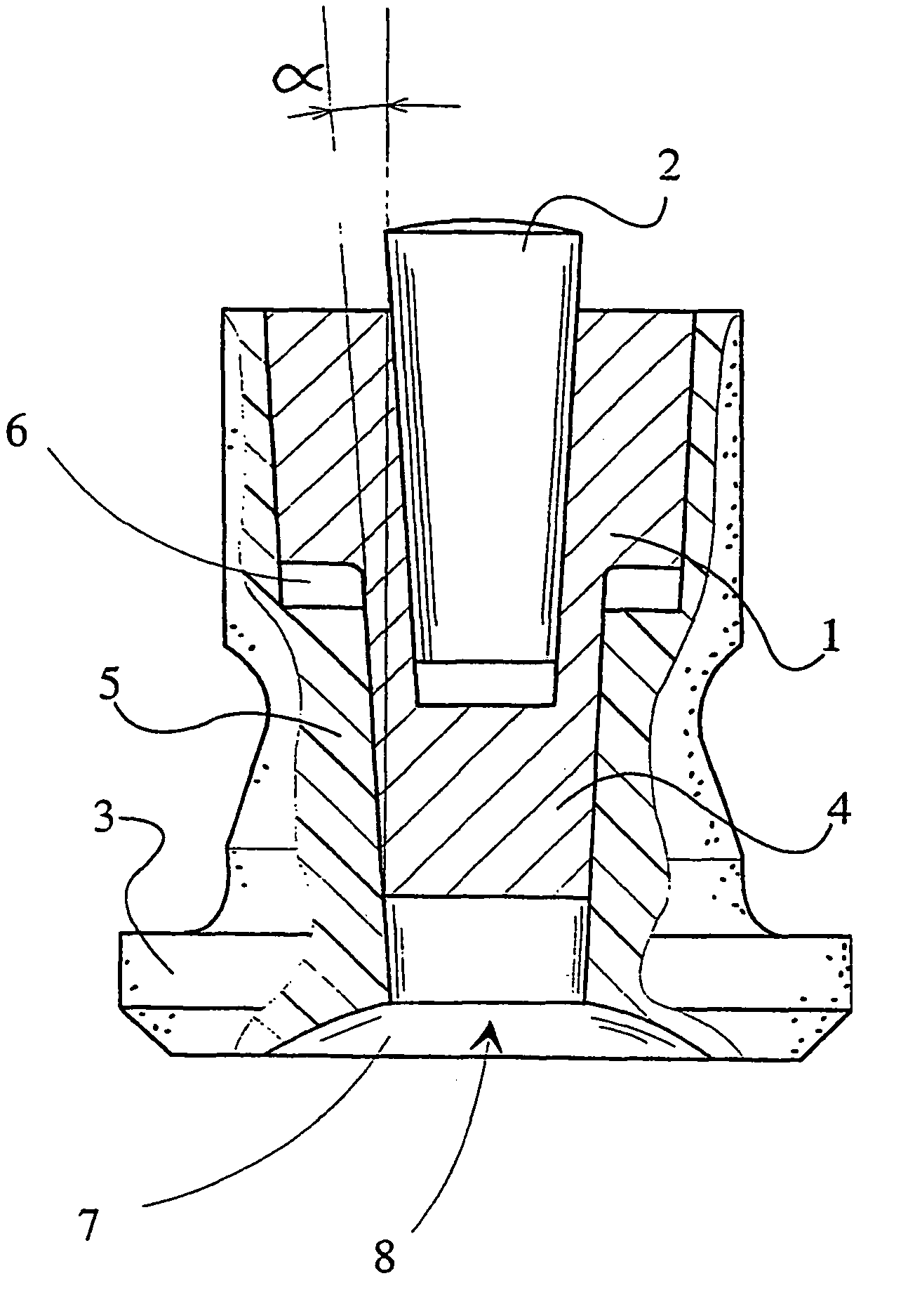
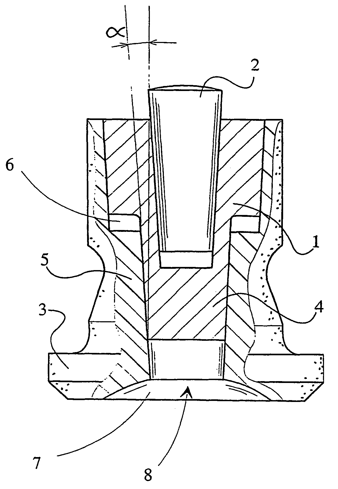
[0011]The stud consists of a socket-formed body portion 1, having a hard metal peak 2 at one end. At its other end, the body has a locking flange 3 retaining the stud in the tyre. The locking flange 3 is made of plastic. The stud body portion 1 has a pin 4 extending towards the locking pin, the tubular sleeve portion 5 of the locking flange being fixed on top of this pin. The body portion 1 is conical so as to be clamped as a wedge into the corresponding conical sleeve portion 5. The body portion 1 has a graded conical surface, its diameter being larger at the hard metal peak 2 than its end 4 at the locking flange 3. At the graded location of the conical surface of the body portion 1 and the conical surface of the sleeve portion 5, there is a hollow annular space 6, which allows the body portion 1 to be wedged deeper when pressing forces are exerted on the stud. The graded feature prevents the body portion 1, if loosened, from being unintentionally pressed into the tyre of the vehic...


PUM


Abstract

The invention relates to a stud for a tyre comprising a socket-formed body portion (1), having at one end a hard metal peak (2) and at its other end a locking flange (3) retaining the stud in the tyre and being made of a light injection-mouldable material, such as plastic, the body portion (1) having a pin (4) extending towards the locking flange, with the tubular sleeve portion (5) of the locking flange fixed on top of this pin. The body portion (1) is conical so as to be clamped as a wedge into the corresponding conical sleeve portion (5).

Description

BACKGROUND OF THE INVENTION[0001]The invention relates to a stud for a tyre comprising a socket-formed body portion having at one end a hard metal peak and at the other end a locking flange retaining the stud in the tyre, and being formed of a light material such as plastic, the body portion having a pin extending towards the locking flange, with the tubular sleeve portion of the locking flange fixed on top of this pin.DESCRIPTION OF THE RELATED ART[0002]As a rule, manufacturers of winter tyres seek to reduce tyre material, i.e. rubber mass, in order to achieve reduced weight of the mass that is without suspension in the car and thus enhanced road-holding characteristics. Winter tyres equipped with lighter studs also cause less wear to the road surface material. As a result of the manufacture of lighter winter tyres, the stud-locking flange gets very close to the ply within a winter tyre. There is a distance of only 2–3 mm between the stud-locking flange and the ply. As a result of ...

Claims


Application Information

Patent Timeline
Patent Type & Authority Patents(United States)
IPC IPC(8): B60C11/16B60C1/00
CPCB60C11/165
Inventor SALAKARI, HEIKKI
Owner TURVANASTA
Learn More