
Flow volume adjustment device for irrigation sprinkler heads
- Summary
- Abstract
- Description
- Claims
- Application Information
AI Technical Summary
Benefits of technology
Problems solved by technology
Method used
Image

Examples
Embodiment Construction
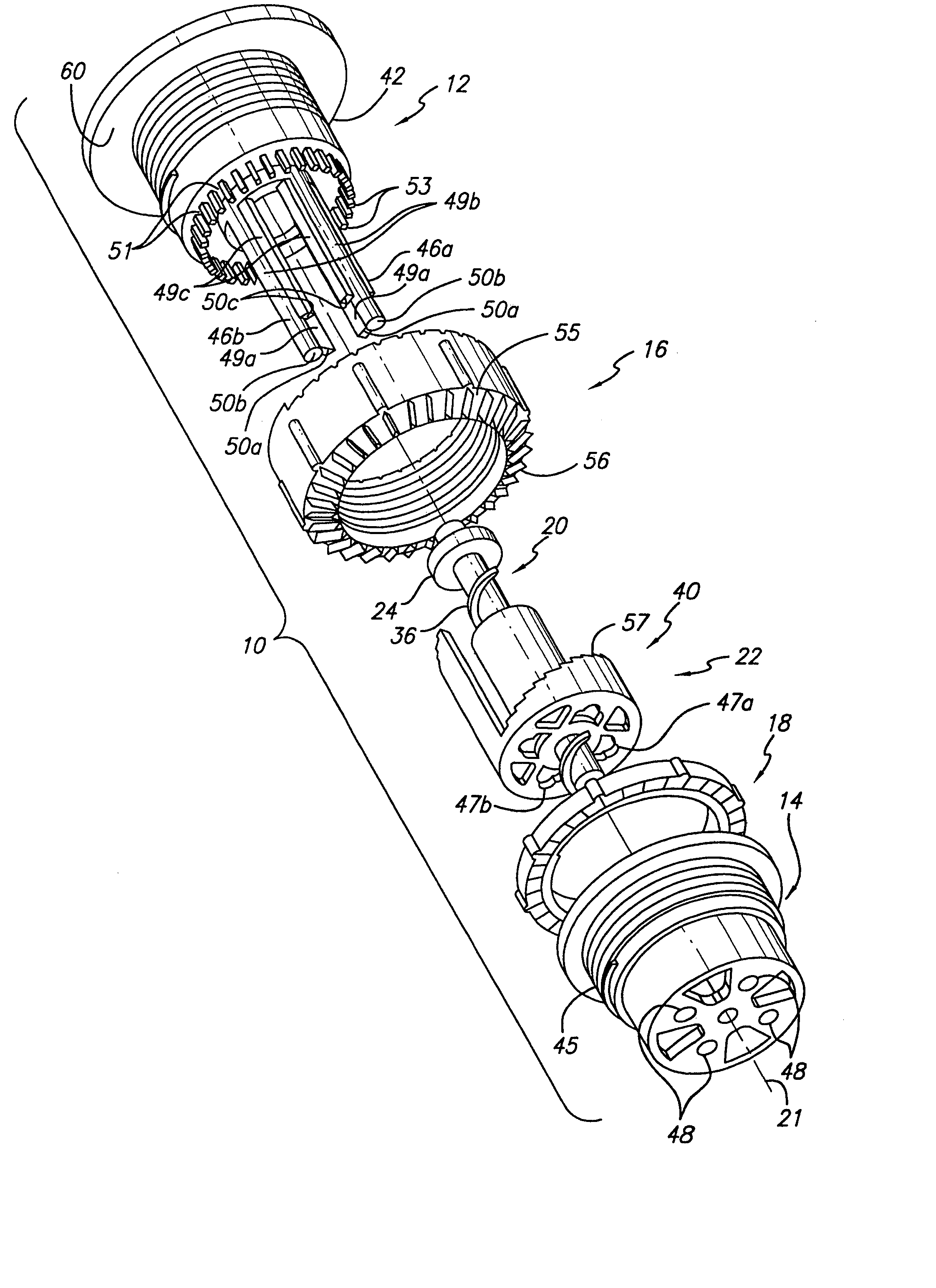
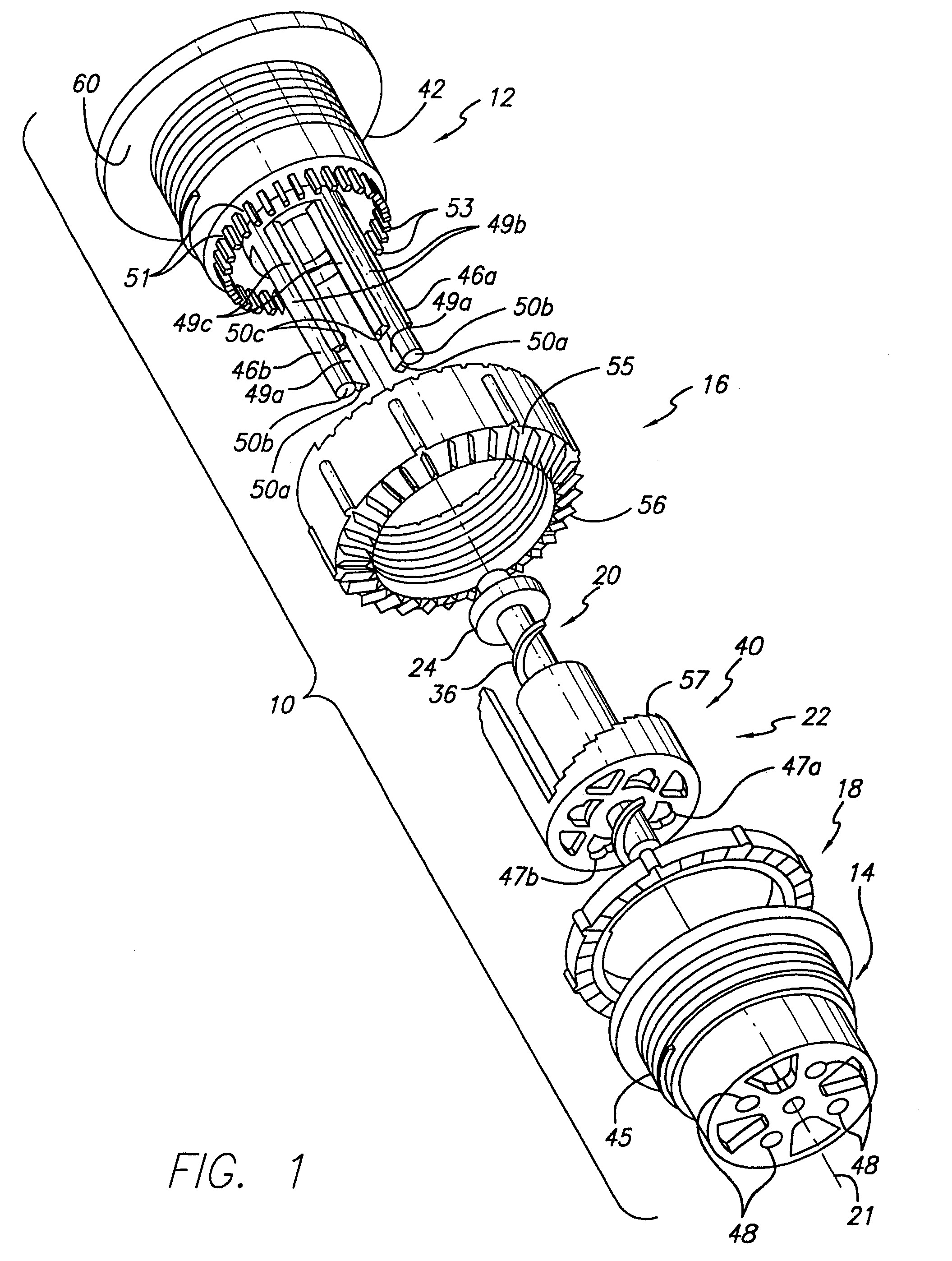
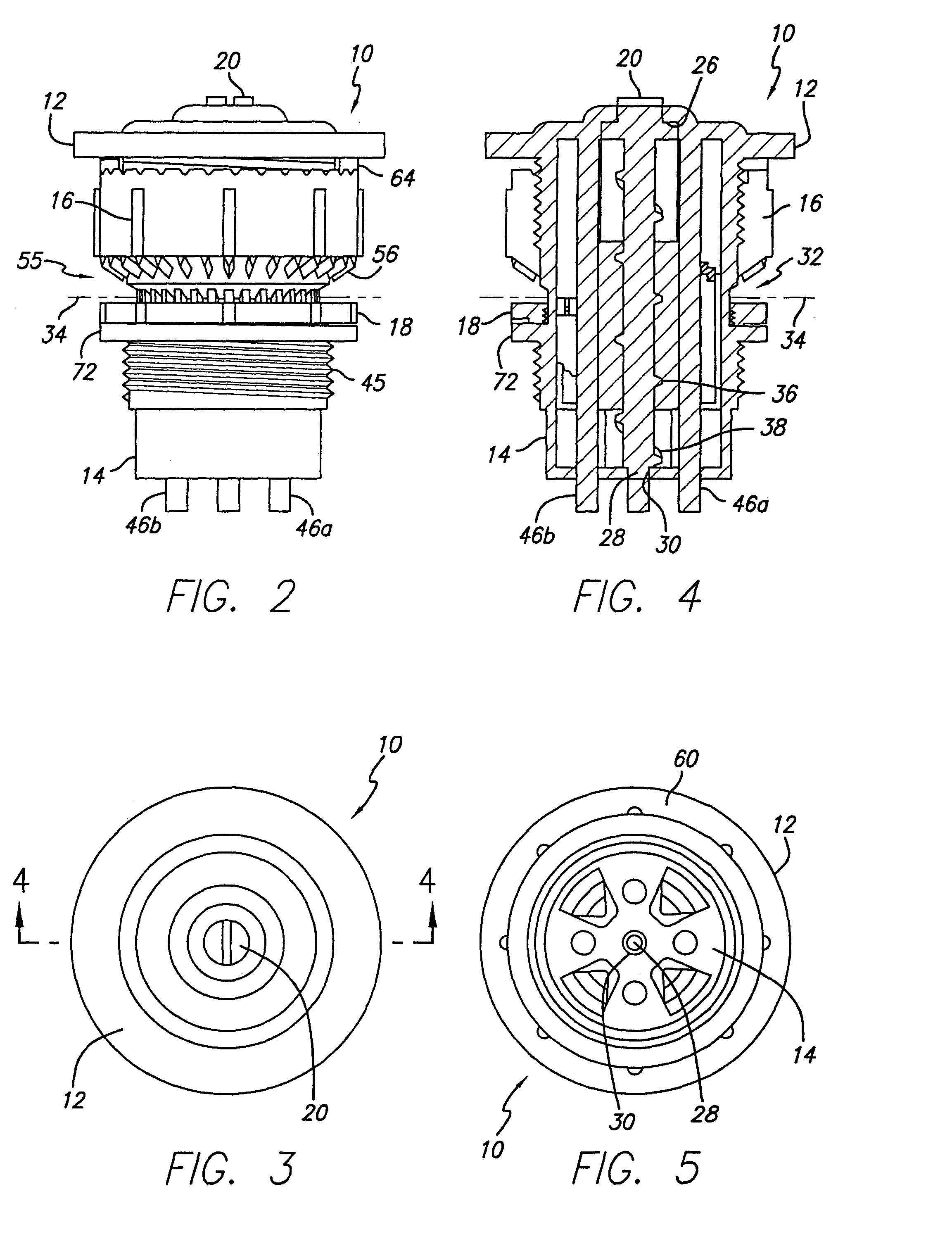
[0027]The present invention provides for an improved adjustable arc spray nozzle that allows for adjustment of the spray arc, the radius, and flow of the water spray provided by the nozzle. As is illustrated in the drawings, the adjustable arc nozzle 10 is assembled from a top member 12, a base member 14, an external upper collar 16, an optional external lower collar 18, and an internal flow adjustment screw 20 extending axially about an axis 21 through an internal helix member 22 between the top member and base member. The internal flow adjustment screw principally allows for control of flow from the nozzle governed by up and down vertical movement of the internal flow adjustment screw proportional to the arc of the spray pattern, but also serves as a device to assure a proper discharge “gap” or orifice size, when the top and base are assembled. This is accomplished by a flange 24 (shown in FIGS. 4 and 6) on the upper end of the screw. The flange mounts on the upper inside edge 26 ...
PUM
 Abstract
Description
Claims
Application Information