Frame structure for vehicle

a frame structure and vehicle technology, applied in the field of vehicle frame structure, can solve the problems of reducing the strength of the bumper beam, reducing the degree of the vehicle body, and reducing the strength of the bumper stays and the bumper beam

Active Publication Date: 2006-04-25
SUBARU CORP
View PDF5 Cites 29 Cited by
  • Summary
  • Abstract
  • Description
  • Claims
  • Application Information

AI Technical Summary

Benefits of technology

[0008]The present invention has been made to solve the foregoing problems of conventional frame structures for a vehicle. An object of the present invention is to provide a frame structure for the vehicle which can effectively disperse and absorb an impact load in a low-speed crash or an offset crash.
[0013]According to the first aspect of the present invention, the pair of diagonal members are arranged so as to extend from the substantially central position of the panel member toward the junctions of the side frames and the cross member. Moreover, the ends of the diagonal members on one side are jointed to the panel member, and the ends of the diagonal members on the other side are jointed to the side frames together with the ends of the cross member. In this way, an impact load in an offset crash is transmitted to the side frame on the uncrashed side through the diagonal member as well as to the side frame on the crashed side, and is thereby dispersed and absorbed. Accordingly, it is possible to optimize the rigidity of the side frames in the longitudinal direction in the offset crash so as to modify a deformation mode of the side frame from a bent mode to an axial crush mode. As a result, the deformation of the vehicle body in the crash is stabilized so as to prevent the deformation of a passenger compartment and to easily rescue a passenger by an improvement in post-crash door operability, thereby improving passenger safety. In addition, even if the optimization of the rigidity causes a degradation in the rigidity of the side frames as compared to conventional side frames, the strength for supporting the bumper beam and the rigidity of the vehicle body are secured by incorporating the diagonal members. Accordingly, the present invention provides an improvement of vehicle safety performance.
[0017]As a result, an impact load received by the bumper beam in a low-speed crash is dispersed and absorbed by the bumper stays and the convex member. Accordingly, a depressed degree of the vehicle body can be decreased in the low-speed crash. Therefore, it is possible to reduce the strength of the bumper stays and of the bumper beam against the impact load. As a consequence, it is possible to reduce the strength of rear ends of the side frames for supporting the reactive force from the bumper stays and from the bumper beam, and thereby to optimize the rigidity and strength of the side frames in the longitudinal direction. In other words, the rear end of the side frame can be rendered more crushable, and the side frame can be stably deformed in the axial crush mode in the offset crash. As a result, it is possible to reduce the weight and the manufacturing costs by reducing the thickness and the length of the respective members. In addition, as the convex member is detachably fixed to the panel member, it is easy to replace the deformed convex member after the crash, and thus a repair cost can be reduced as well. Incidentally, although the more easily crushable rear end of the side frame may decrease a crash energy absorption, such a defect can be fully compensated by providing the diagonal members.
[0018]As a result, it is possible to provide a frame structure for the vehicle which can effectively disperse and absorb the impact load in the low-speed crash or the offset crash.

Problems solved by technology

In this case, increase in a thickness and a length of the respective members for the rigidity of the rear frames 1 and 1′ and the strength of the bumper stays 4 and 4′ against the impact load from the back side as well as the bumper beam 5 would result in further adding manufacturing costs and weight thereof.
When the rear frame 1′ receiving the impact load is bent without collapsing in an axial direction, an absorption of the impact load may not be achieved as designed, whereby an unintentional deformation of the rear floor above the rear frames 1 and 1′ may hurt passengers in the vehicle (see, for example, Japanese Patent Application Laid-Open No.

Method used


Image

  • Frame structure for vehicle
  • Frame structure for vehicle
  • Frame structure for vehicle

Examples


Embodiment Construction

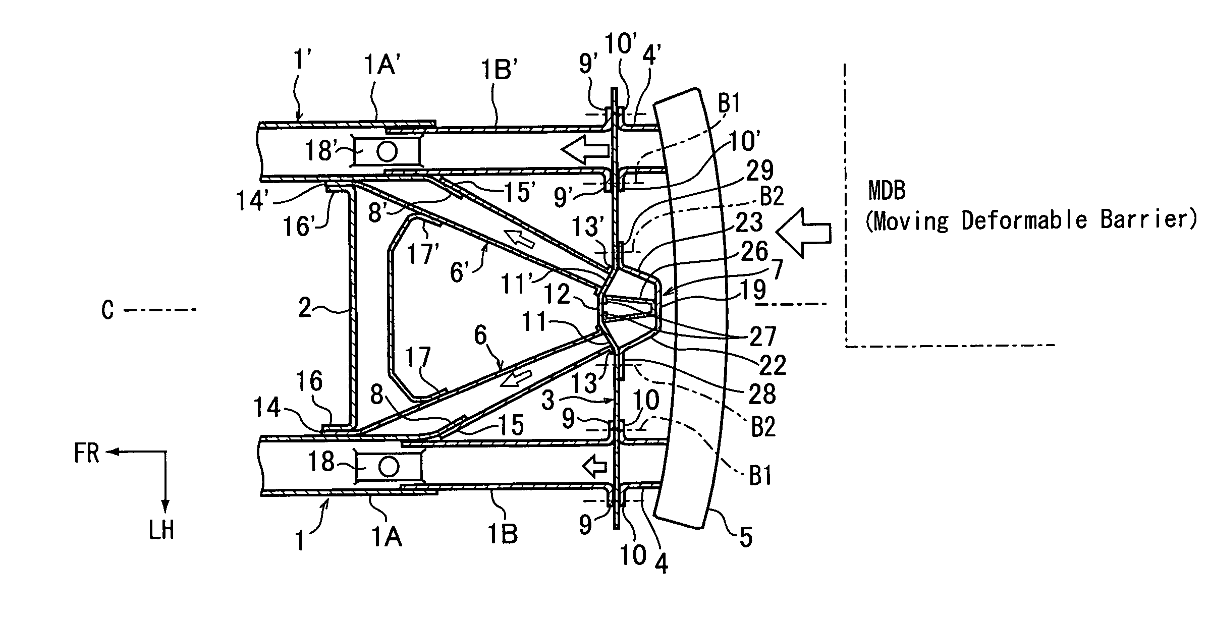
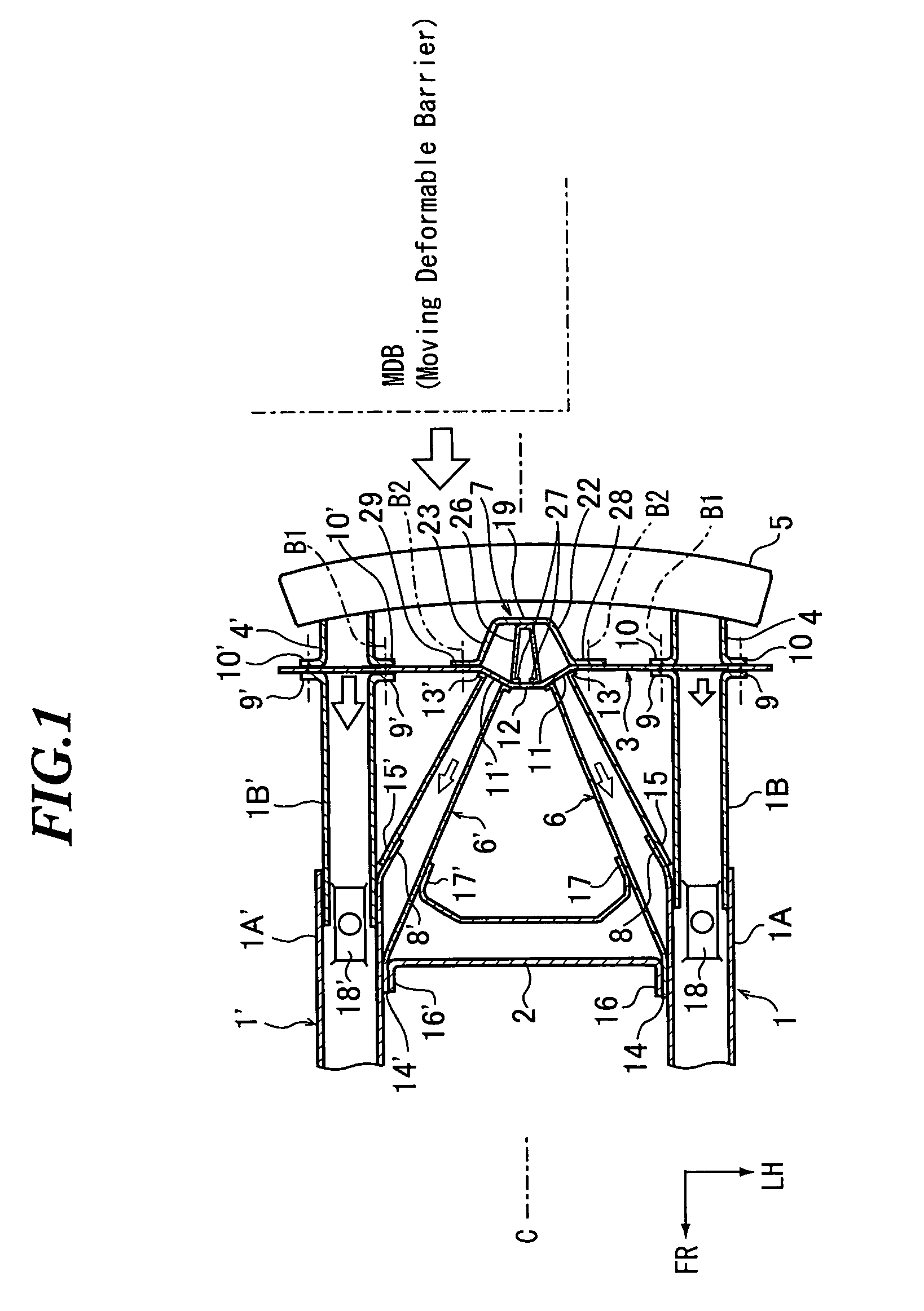
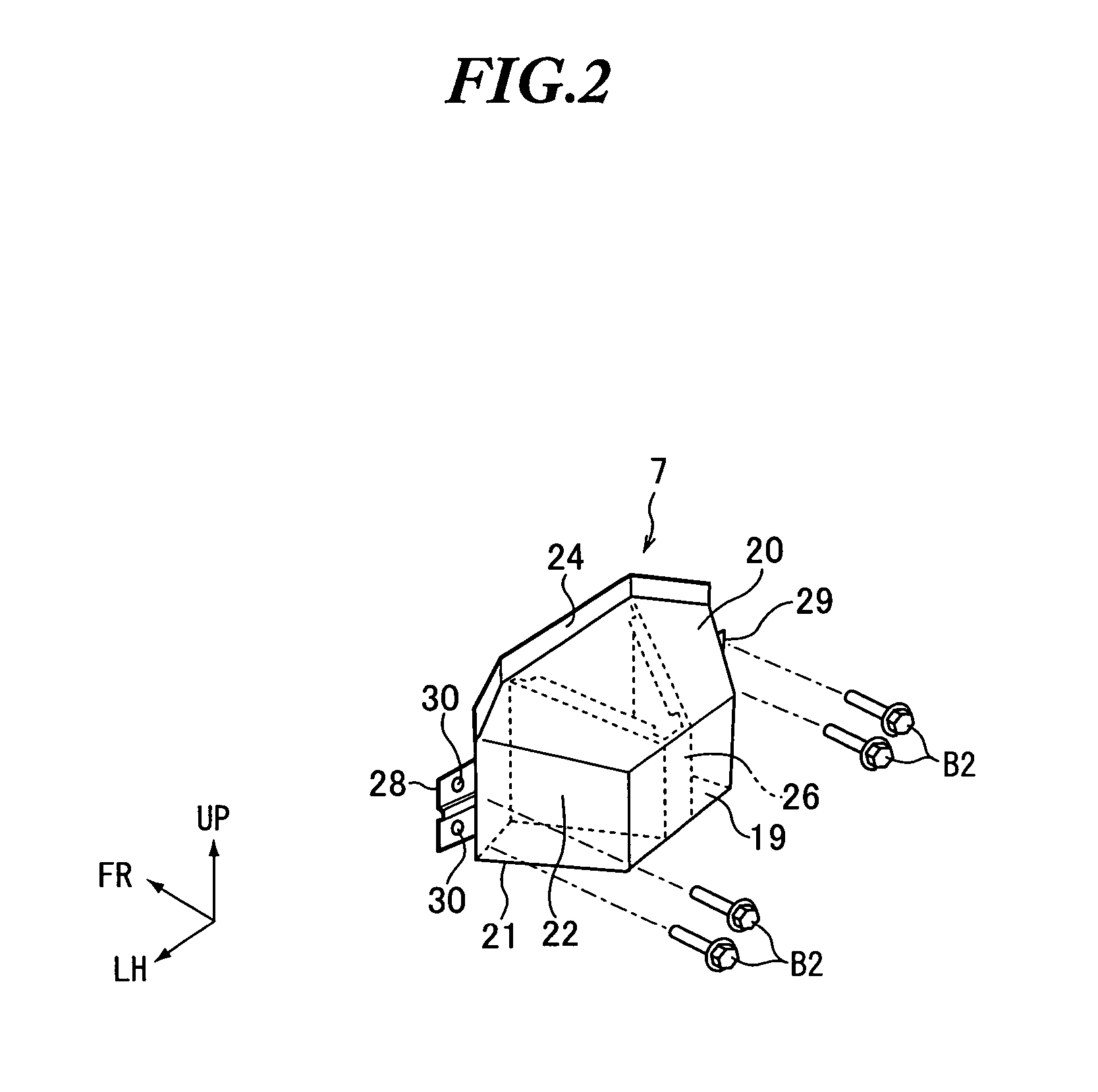
[0025]The present invention realizes a frame structure for a vehicle capable of effectively dispersing and absorbing an impact load in a low-speed crash or an offset crash by providing a pair of diagonal members and a convex member.

[0026]An embodiment considered as the most preferred embodiment of the present invention will now be described in detail with reference to FIGS. 1 to 3. FIG. 1 is a plan view showing the embodiment in which the present invention is applied to a rear frame structure for a vehicle. FIG. 2 is a perspective view of a convex member in the embodiment. FIG. 3 is the plan view showing a low-speed rear crash in the embodiment. Constituents in these drawings which are essentially similar to those in the conventional example are designated by the same reference numerals as in the conventional example.

[0027]A rear frame structure will be here described according to the present invention. As shown in FIGS. 1 to 3, the rear frame structure includes a pair of diagonal m...


PUM


Abstract

A pair of diagonal members are arranged to extend from a substantially central position of a rear end panel extending in a widthwise direction of a vehicle body toward respective junctions of rear frames and a cross member. An end of each of the diagonal members is jointed to the rear end panel, and the other end thereof is jointed to the rear frame together with an end of the cross member. In addition, a guard block protruding toward a bumper beam is detachably fixed to the substantially central position of the rear end panel. Thus, such a frame structure for a vehicle can disperse and absorb an impact load in a low-speed crash or an offset crash.

Description

BACKGROUND OF THE INVENTION[0001]This invention relates to a frame structure for a vehicle.[0002]The present application claims priority from Japanese Patent Application No. 2003-353946, the disclosure of which is incorporated herein by reference.[0003]Conventionally, as shown in FIG. 4, rear side frames (hereinafter referred to as rear frames) 1 and 1′ disposed on both right and left sides of a vehicle body have been connected to each other through a cross member 2 which extends in a widthwise direction of the vehicle body below a rear floor, and have been configured to maintain a strength for supporting a bumper beam 5 fixed in a cantilever manner through a rear end panel 3 and through bumper stays 4 and 4′ and to maintain a rigidity of the vehicle body.[0004]Incidentally, in this conventional frame structure, an impact load applied from a back side of the vehicle body to the bumper beam 5 due to a crash, for example, is transmitted through the bumper stays 4 and 4′ to the respect...

Claims


Application Information

Patent Timeline
Patent Type & Authority Patents(United States)
IPC IPC(8): B62D25/20B62D21/15
CPCB62D21/152
Inventor MATSUDA, HIROYUKI
Owner SUBARU CORP
Why Eureka
Try Eureka