Method and apparatus for correcting sensor signal in temperature

a sensor signal and temperature technology, applied in the direction of instruments, heat measurement, turn-sensitive devices, etc., can solve the problems of offset correction, inability to accurately correct the zero point correction, and increase the cost of the signal processing circuit, so as to reduce the total processing time of the correction of the sensor output signal

Active Publication Date: 2006-04-25
DENSO CORP
View PDF12 Cites 25 Cited by
  • Summary
  • Abstract
  • Description
  • Claims
  • Application Information

AI Technical Summary

Benefits of technology

[0015]Accordingly, it is an object of the present invention to provide a method and an apparatus for correcting a sensor signal in an environmental temperature, which are capable of decreasing a total processing time of the correction of the sensor output signal in the environmental temperature.

Problems solved by technology

This absolute correction, however, fails to accurately correct the zero point correction, in other words, offset correction, of the temperature dependent characteristic of the sensor.
The disclosed signal processing circuit, however, requires the microcomputer 5 for performing the zero point correction, causing the cost of the signal processing circuit to rise.

Method used


Image

  • Method and apparatus for correcting sensor signal in temperature
  • Method and apparatus for correcting sensor signal in temperature
  • Method and apparatus for correcting sensor signal in temperature

Examples


first embodiment

[0031](First Embodiment)

[0032]As a first embodiment of the present invention, a sensor signal correcting apparatus for a yaw rate sensor installed in a vehicle, for which the present invention is applied, will be described hereinafter with reference to FIGS. 1 and 2.

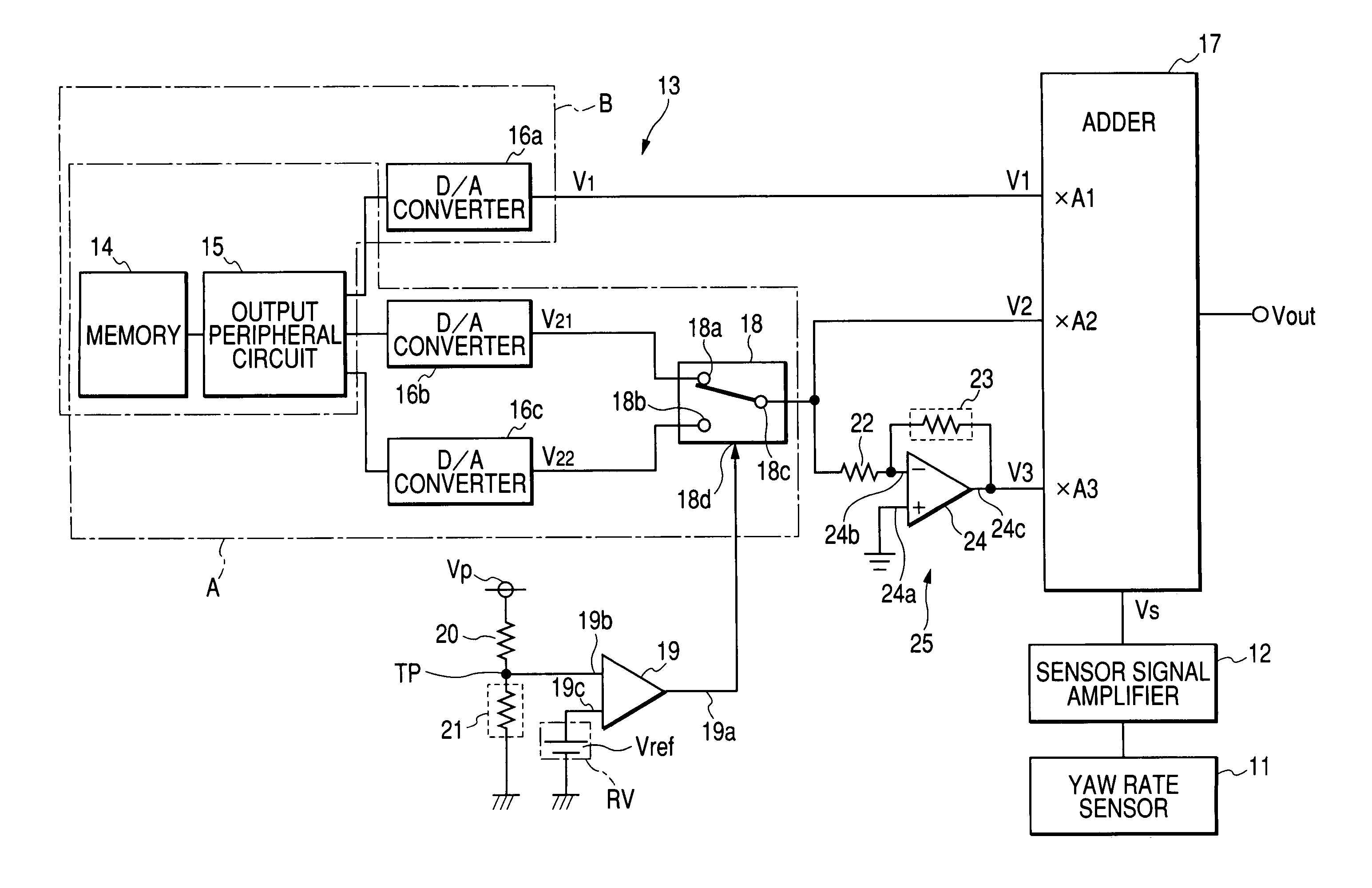
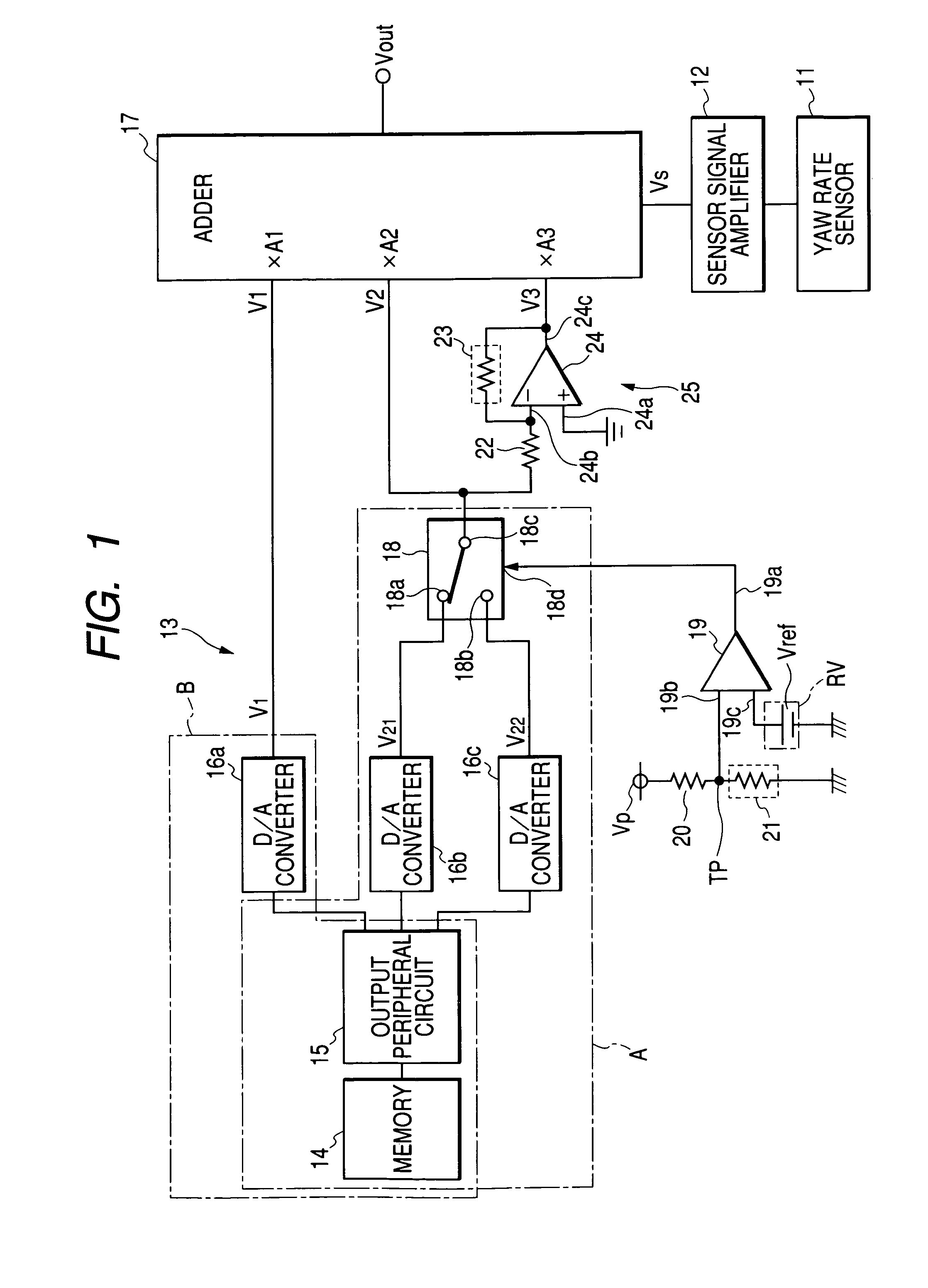
[0033]FIG. 1 is a block diagram schematically illustrating the yaw rate sensor 11, a sensor signal amplifier 12, and the sensor signal correcting apparatus 13 according to the first embodiment.

[0034]The yaw rate sensor 11 installed in the vehicle, as an example of dynamic volume sensors, is composed of an oscillation member made of, for example, piezoelectric element (not shown), such as PZT (lead (Pb) zirconia (Zr) titanate (Ti)) ceramic so that the piezoelectric element is formed as, for example a fork-like shape. The yaw rate sensor 11 is designed, as well known, to use Coriolis force to sense a yaw rate of the vehicle. In particular, the yaw rate sensor 11 is provided in the vehicle in order to keep the vehicle's run...

second embodiment

[0118](Second Embodiment)

[0119]Next, a sensor signal correcting apparatus 30 according to a second embodiment of the present invention will be explained hereinafter.

[0120]Incidentally, elements of the sensor signal correcting apparatus 30 according to the second embodiment, which are substantially identical with those of the sensor signal correcting apparatus 13 according to the first embodiment, are assigned to the same reference characteristics of the sensor signal correcting apparatus 13 shown in FIG. 1, and explanations thereabout are omitted or simplified.

[0121]FIG. 3 is a block diagram schematically illustrating the yaw rate sensor 11, the sensor signal amplifier 12, and the sensor signal correcting apparatus 30 according to the second embodiment.

[0122]The sensor signal correcting apparatus 30 is composed of, in place of the memory 14 and output peripheral circuit 15, a plurality of, such as three pair of variable resistors 31a, 31b, 32a, 32b, and 33a, 33b.

[0123]The paired va...


PUM

PropertyMeasurementUnit
temperatureaaaaaaaaaa
temperature T1aaaaaaaaaa

Abstract

A slope correction signal setting unit is configured to output selectively one of a plurality of direct current signals according to the sensed temperature parameter signal. Levels of the plurality of direct current signals are determined to correspond to the predetermined temperature dependent characteristic of the sensor signal. An analog amplifying circuit is connected to the slope correction signal setting unit and configured to amplify the outputted direct current signal according to the sensed temperature parameter signal. An analog arithmetic circuit is connected to the analog amplifying circuit and configured to carry out a predetermined arithmetic operation based on the amplified direct current signal and the sensor signal.

Description

BACKGROUND OF THE INVENTION[0001]The present invention relates to a method and an apparatus for carrying out zero point corrections of temperature dependent characteristics of output signal signals of sensors.[0002]Various types of sensors have their varying temperature dependent characteristics due to environmental temperatures therearound and piece-to-piece variations. Such a sensor has complex temperature dependent factors so that the temperature dependent characteristic of the sensor is usually different from a simple linear characteristic.[0003]In order to correct the temperature dependent characteristic of the sensor, the environmental temperature around the sensor is measured as a temperature parameter signal, and the absolute level of the sensor signal outputted from the sensor, which includes an error depending on the environmental temperature, is corrected based on the measured temperature parameter signal. This results in that the slope of the sensor signal with respect t...

Claims


Application Information

Patent Timeline
Patent Type & Authority Patents(United States)
IPC IPC(8): G01K13/00G01K7/00G01P3/00G01C19/56G01C19/5614G01D3/02G01D3/028G01D3/036G01D18/00
CPCG01D3/022G01D18/008G01D3/0365
Inventor OTSUKA, YUZURU
Owner DENSO CORP
Why Eureka
Try Eureka