Vertebral arthrodesis equipment

a technology of arthrodesis equipment and articular cartilage, which is applied in the field of articular cartilage equipment, can solve the problems of limited implementation of this hook, inability to adapt, and provoking doubts about the perfect resistance of the assembly that it allows, and achieves the effect of facilitating the implantation of equipmen

Inactive Publication Date: 2006-04-25
TAYLOR AS +4
View PDF13 Cites 103 Cited by
  • Summary
  • Abstract
  • Description
  • Claims
  • Application Information

AI Technical Summary

Benefits of technology

[0022]Because of the cavity and the convex base, the threaded rod may be aligned towards the stirrup piece, which itself has already been engaged about the shoring rod. This alignment makes it easier for the eyelet on the stirrup piece to be engaged with this threaded rod.
[0023]The nut may then be engaged on the threaded rod and tightened, which has the effect of drawing said concave face of the stirrup piece into contact with said portion of the spherical wall of the boss and then, when such contact is made, and because of the offset between the two centres indicated previously, of drawing said threaded rod in a direction substantially perpendicular to the base as the nut is tightened further.
[0024]These means of assembly thus facilitate the implantation of the equipment and enable the shoring rod to be positioned progressively relative to the anchoring assemblies that constitute this equipment, which have been positioned on the vertebrae beforehand.

Problems solved by technology

However, the possibilities for implementing this hook are limited to one pedicle support point, which does not allow of adaptation for the various situations that may arise.
In extreme cases, the existing hook may also provoke doubts regarding the perfect resistance of the assembly that it allows.
In addition, one significant disadvantage of the existing “tuning fork” (“tulip”) hooks is that occasionally considerable effort is required to locate the rods inside the seating for these rods.
When the pedicles are small in size, as is the case for thoracic vertebrae, particularly vertebrae D1 to D4, there is a danger that the pedicle may break and it is necessary to rely on hooks rather than screws.
In view of the limitations described in the aforegoing, the existing hooks are not ideally suited for all situations that may arise.
A further disadvantage of the existing hooks is that their height is substantial due to the height of the said walls defining the seatings for a shoring rod.
This height is not particularly inconvenient when the tissues are fairly thick, as is the case at the level of the lumbar vertebrae, but it does create difficulties when tissues become relatively thin, as is the case at the level of the thoracic vertebrae, when the equipment may be felt under the skin.

Method used


Image

  • Vertebral arthrodesis equipment
  • Vertebral arthrodesis equipment
  • Vertebral arthrodesis equipment

Examples


Embodiment Construction

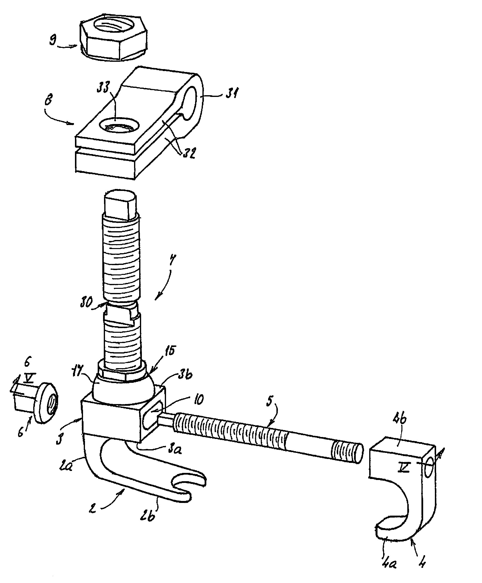
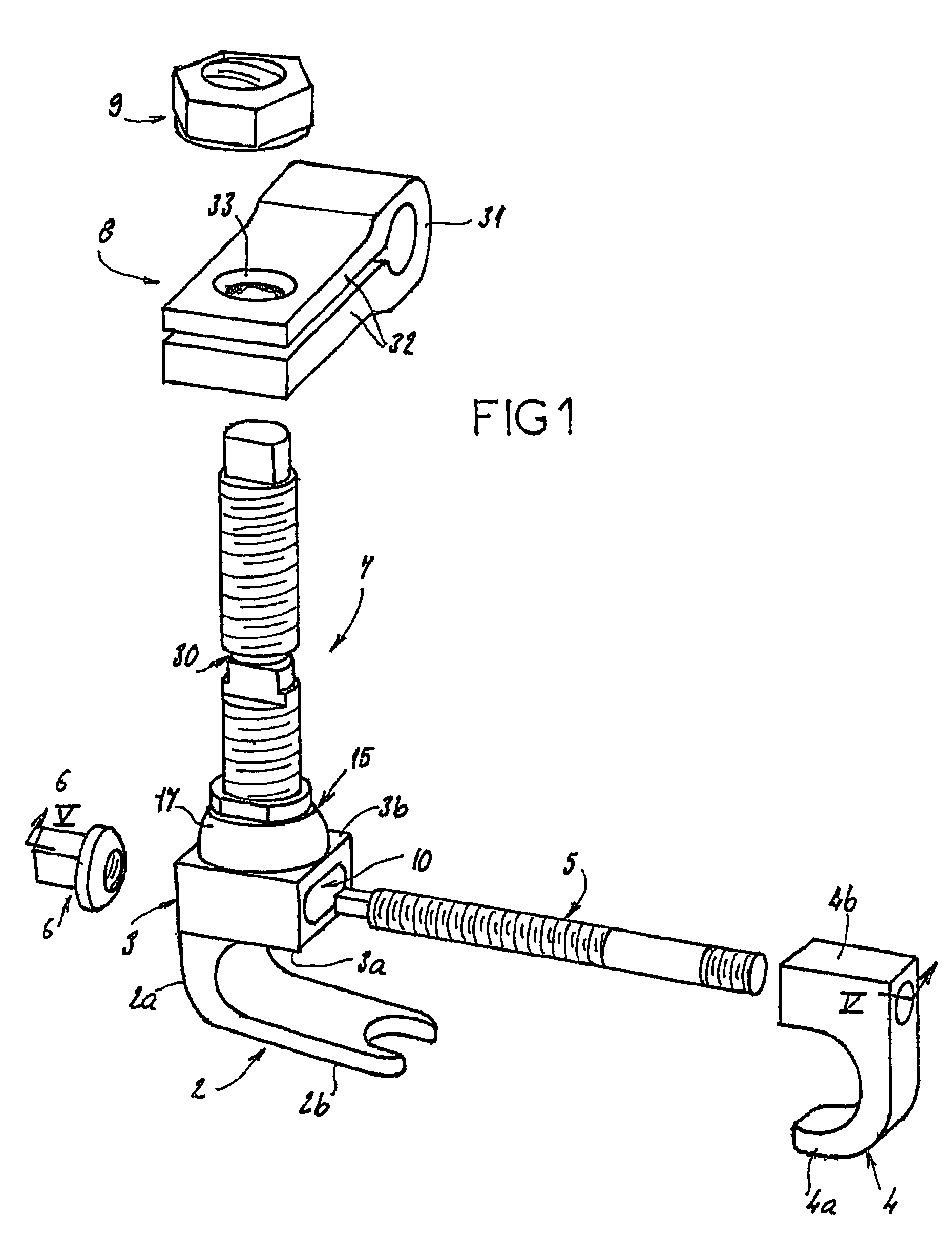
[0029]FIG. 1 represents an anchorage assembly 1 forming part of a vertebral arthrodesis equipment.

[0030]This equipment includes two shoring rods, designed to be to be disposed parallel to one another and on either side of the vertebrae, and anchoring members for anchoring these rods to the vertebrae. These anchoring members may be pedicle screws and / or one or more anchoring assemblies 1. The equipment may further include cross-members that are designed to draw the shoring rods transversely together progressively, for preserving their position relative to one another.

[0031]These rods, pedicle screws and cross-members are known in and of themselves and are therefore not specifically described.

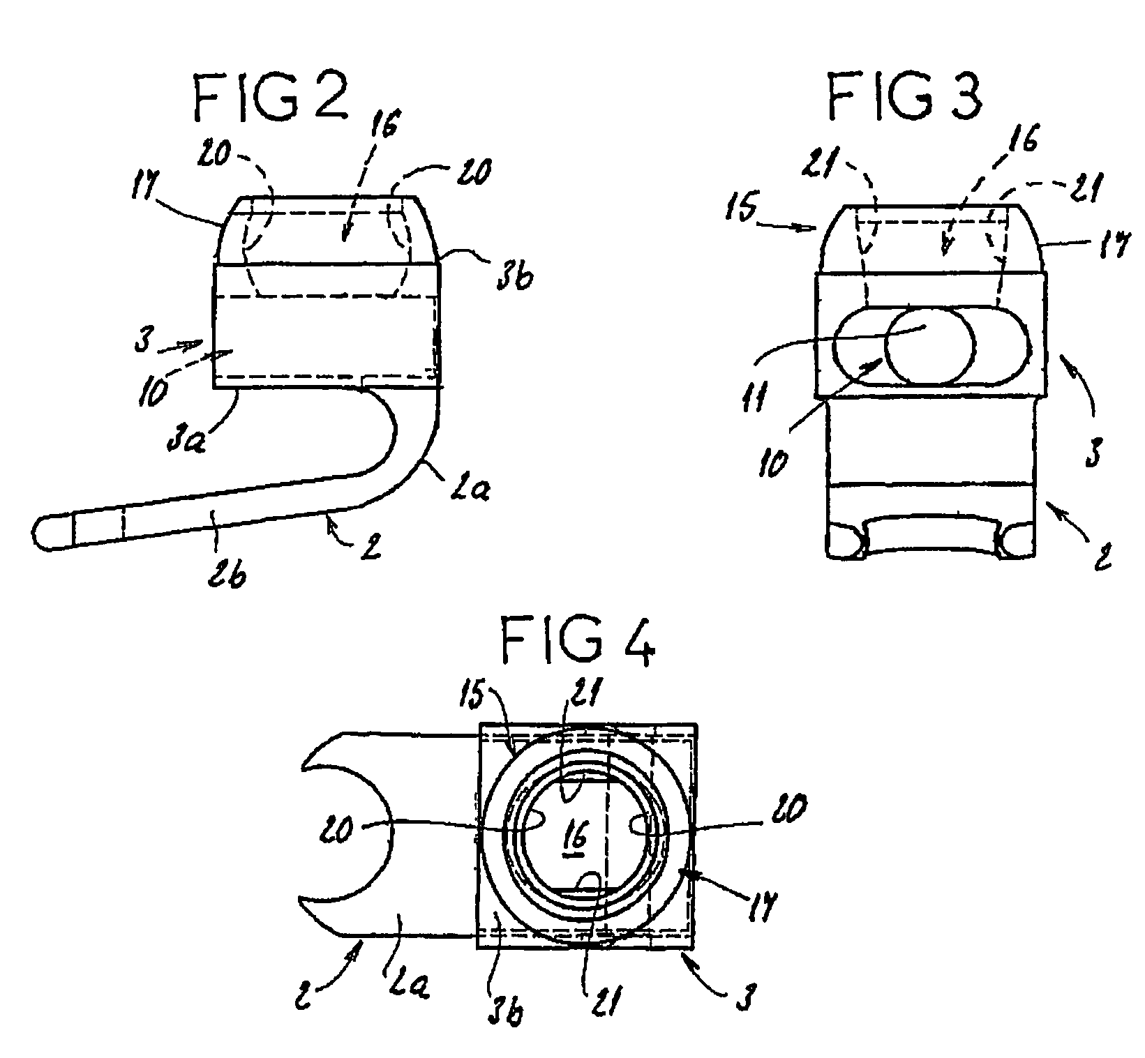
[0032]As is shown in FIG. 1, anchoring assembly 1 comprises a hook 2 integral with a parallelepiped base 3, a hook-shaped component 4 attached to a threaded rod 5, a screw 6 that may be screwed onto this threaded rod 5, a threaded rod 7, a stirrup piece 8, and a nut 9.

[0033]Hook 2 is furnished wi...


PUM


Abstract

An equipment includes at least a shoring rod and at least an anchoring assembly of the shoring rod to a vertebra; each anchoring assembly comprises a base integral with a hook which has substantially planar part, extending in a parallel plane, or forming a slight angle, less than 15 degrees, with the base. The base has a hole which runs right through it, having an oblong cross-section, and the anchoring assembly comprises a hook-shaped component whereof the part corresponding to the base of the hook is linked to a threaded rod capable of being engaged in the hole with the possibly of pivoting about an axis and of displacement in the plane, and capable of receiving a screw.

Description

CROSS REFERENCE TO RELATED APPLICATION[0001]This is the 35 USC 371 national stage of international application PCT / FR01 / 03411 filed on Nov. 5, 2001, which designated the United States of America.FIELD OF THE INVENTION[0002]The present invention relates to a vertebral arthrodesis equipment.BACKGROUND OF THE INVENTION[0003]Equipment of such kind generally includes two shoring rods designed to be disposed parallel to one another on either side of the vertebrae to be treated, and assemblies for anchoring these rods to the vertebrae, in the form of hooks or pedicle screws. This equipment may also include cross-members that approach these rods incrementally, for preserving their position relative to one another.[0004]In order to attach a shoring rod to an anchoring assembly, the design has provided for the inclusion of two facing walls on the proximal portion of the anchoring assembly, these walls defining a seating for the rod therebetween and furnished with means, such as a threaded or ...

Claims


Application Information

Patent Timeline
Patent Type & Authority Patents(United States)
IPC IPC(8): A61B17/70A61B17/58A61B90/00
CPCA61B17/7037A61B17/7041A61B17/7056A61B17/7047A61B2019/307A61B2090/037
Inventor TAYLORVILLARET, BERNARDPARISINI, PATRIZIOCLEMENT, JEAN-LUCADAM, YVES
Owner TAYLOR AS
Why Eureka
Try Eureka