Receptacle

a technology for receptacles and trays, which is applied in the direction of circuit-breaking switches, electrical apparatus casings/cabinets/drawers, coupling device connections, etc., and can solve problems such as insulation and wiring structure, unable to detect and test arc faults, and damaged cables

Active Publication Date: 2006-04-25
SEOCHANG ELECTRONIC COMMUNICATION CO LTD
View PDF8 Cites 33 Cited by
  • Summary
  • Abstract
  • Description
  • Claims
  • Application Information

AI Technical Summary

Benefits of technology

[0026]It is a second object of the present invention to provide a receptacle that is designed to be reset by a simple operation after a fault test.
[0027]It is a third object of the present invention to provide a receptacle that can detect a wire connection fault when a wire is originally distributed.

Problems solved by technology

The cable may be damaged by a variety of causes such as thermal degradation, deterioration, moisture, and damage by rodents.
Although the above-described conventional receptacle is designed to be able to detect and test the ground fault, it still has a problem that it cannot detect and test the arc fault caused by a wire damage, a mechanical and electrical stress by an excessive current and an excessive use, a wire connection defect, a mechanical damage of an insulation and wiring structure, and the like.
In addition, the conventional receptacle has a problem that the reset operation is very complicated after the fault test.
Further more, since the conventional receptacle is designed not to test the wire connection fault when the wire is originally distributed, there may be an accident such as a malfunction and damage of an electric device and a fire due to the wire connection fault.

Method used


Image

  • Receptacle
  • Receptacle
  • Receptacle

Examples


first embodiment

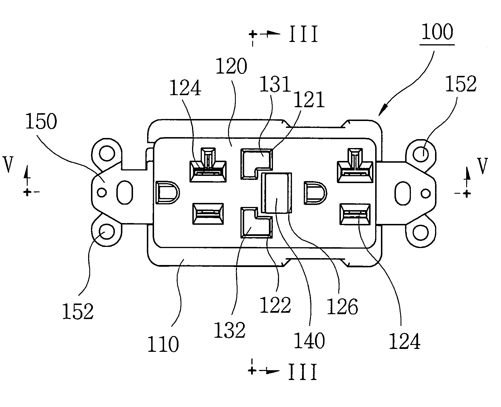
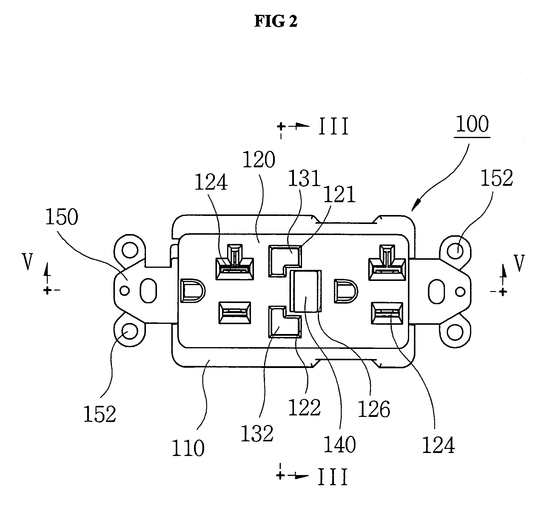
[0064]FIG. 2 shows a plane view of a receptacle according to a first embodiment of the present invention.

[0065]As shown in the drawing, a receptacle 100 includes an insulated outer case 110, a cover 120 coupled on a top of the insulated outer case 110, first and second buttons 131 and 132 disposed in the outer case 110 and externally exposed through the cover 120, and a reset button 140 disposed in the outer case 110 and externally exposed through the cover 120.

[0066]Coupled between the outer case 110 and the cover 120 is a yoke 150 provided at opposite sides with coupling holes 152 to allow the receptacle to be easily fixed on a building wall, on which a service-wire is distributed, by bolts, screws, and the like.

[0067]FIG. 3 shows a sectional view taken along line III—III of FIG. 2.

[0068]Referring to FIGS. 2 and 3, the insulated outer case 110 is provided at inner-opposite sides with first and second receiving portions 111 and 112 for respectively receiving the first and second te...

second embodiment

[0121]FIG. 10 shows an enlarged perspective view illustrating first and second test buttons of a receptacle according to a second embodiment of the present invention.

[0122]In this embodiment, first and second tap buttons 241 and 242 are respectively attached on the contacting portions 1312 and 1322 of the respective first and second test buttons 131 and 132.

[0123]As shown in the drawing, when pressing force is applied to one of the first and second test buttons 241 and 242, the corresponding tab button 241 (242) operates the corresponding trip switch 171 (172), thereby performing the test operation through the processes identical to those described in the first embodiment.

[0124]In this embodiment, since the first and second test buttons 131 and 132 for the ground and arc fault tests are designed to operate the first and second tab buttons 241 and 242 without generating a short circuit on an integrated circuit, the test can be more safely realized.

third embodiment

[0125]FIG. 11 shows an exploded perspective view illustrating a reset button, reset guide, and locking portion of a receptacle according to a third embodiment of the present invention.

[0126]A reset button 140 of this embodiment includes a press portion 142 externally exposed through the cover 120 (see FIG. 2) and an extending shaft 144 extending downward from the press portion 142.

[0127]The extending shaft 144 is provided at an outer circumference with a hook groove 146. The extending shaft 144 is further provided at a portion below the hook groove 146 with an intermitting groove 148 having a semi-cylindrical shape.

[0128]The reset button 140 is disposed to be movable in a vertical direction of the outer case 110 (see FIG. 2) and is biased upward by a second spring 182.

[0129]A reset guide 190 is provided with an insertion hole 192 through which the extending shaft 144 of the reset button 140 is inserted, a hook passage 198 formed in a perpendicular direction with respect to the inser...


PUM


Abstract

A receptacle includes an insulated outer case, first and second trip switches formed on an inner bottom of the insulated case, a reset switch formed on the inner bottom of the insulated outer case, a cover disposed on a top of the outer case, first and second test buttons disposed in the insulated outer case to be movable in a vertical direction, each of the first and second test buttons having a bottom adjacent to the corresponding trip switch and a top exposed through the cover, a first spring for biasing the first and second test buttons to an initial position, a reset button disposed in the insulated outer case to be movable in a vertical direction, the reset button having a bottom adjacent to the reset switch and a top exposed through the cover, and a locking portion for selectively locking the reset button in response to the vertical motion of the first and second test button.

Description

BACKGROUND OF THE INVENTION[0001]1. Field of the Invention[0002]The present invention relates to a receptacle used in an electric power distribution system and more particularly, to a receptacle that can prevent an accident such as a damage of an electric device and a fire in advance, which may be caused by a wire connection fault or an arc fault, by detecting an error caused by the wire connection fault when a service wire is originally distributed in the receptacle and by detecting an error caused by the arc fault generated in a current during the use of the current.[0003]2. Description of the Related Art[0004]Generally, a low voltage (600 V or less) network is used for a distributing board at a specific area such as a city, an industrial area, and a commercial area.[0005]Particularly, a cable of the network is laid under the ground, being designed to be introduced from at least one location.[0006]The cable may be damaged by a variety of causes such as thermal degradation, deterio...

Claims


Application Information

Patent Timeline
Patent Type & Authority Patents(United States)
IPC IPC(8): H01H9/02H01H83/04H01R13/713
CPCH01R13/713H01H83/04
Inventor KIM, CHEON-YOUNKIM, DONG SEBLEE, SUL-KILLIM, KI-YOUNGSONG, SEOK-WONKIM, DAE-GUN
Owner SEOCHANG ELECTRONIC COMMUNICATION CO LTD
Why Eureka
Try Eureka