Hybrid synchronous electric machine

a hybrid electric machine and hybrid technology, applied in the direction of instruments, horology, structural associations, etc., can solve the problems of induced electric current, large energy loss of the described type, and consume much more energy than in the corresponding parts of the conventional motor, so as to achieve low eddy current loss

Inactive Publication Date: 2006-04-25
HARMONIC DRIVE SYST IND CO LTD
View PDF20 Cites 27 Cited by
  • Summary
  • Abstract
  • Description
  • Claims
  • Application Information

AI Technical Summary

Benefits of technology

[0017]The hybrid synchronous motor according the present invention has low eddy current losses because eddy currents in cogged iron rings are impeded by cross-cut insulating gaps in these same iron rings, while eddy currents in all passive parts of the motor (like rotor armature, stator armature, and ball bearings) are negligible since the current induced in the copper ring neutralizes all the dissipated magnetic flux outside the active area of the motor. Further, this motor is very compact, strong and mechanically stable, despite low eddy current losses.

Problems solved by technology

However, at high speed when magnetic fluxes in the motor alternate with considerably high frequency, we meet the problem of induced electric currents.
They may consume much more energy than in corresponding parts of conventional motors with longitudinal magnetic flux.
Energy losses of the described type are great especially when motor runs at high speed and torque (therefore, at high power); in this case they may be much greater than all other losses taken together.
Energy efficiency at high values of mechanical power is then seriously spoiled and the motor may overhear.
One partial solution could be replacement of metal as the building material in passive parts (especially in rotor and stator armature) with electrically insulating materials (like ceramics or plastic materials), but usually such solutions are either too expensive (for ceramics) or mechanically inadequate (for plastics).
Consequently, there is a need in the art for additional high-power hybrid electric machines, which have coaxial coils and transverse magnetic flux, yet their construction does not permit flow of induced electric currents in coaxial parts of the motor.

Method used


Image

  • Hybrid synchronous electric machine
  • Hybrid synchronous electric machine
  • Hybrid synchronous electric machine

Examples


Embodiment Construction

[0039]With respect to the drawings, examples of the present invention will now be explained.

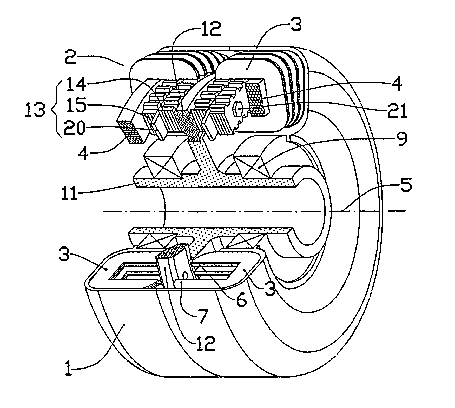
[0040]In FIG. 1, a first embodiment (example A) of a two-phase synchronous hybrid electric machine with transverse magnetic flux according to the invention is shown. To each side of the stator armature (1) is fixed a circular array (2) of U-shaped stator yokes (3) which encircle the stator winding (4) of the corresponding phase. The windings (4) are coaxial with the motor axis (5).

[0041]Stator yokes (3) with salient poles (6, 7) are more precisely shown in FIG. 3. The yokes may be of bulk iron but it is better that the yokes (3) are lamination packages, as it is shown in FIGS. 1 and 3.

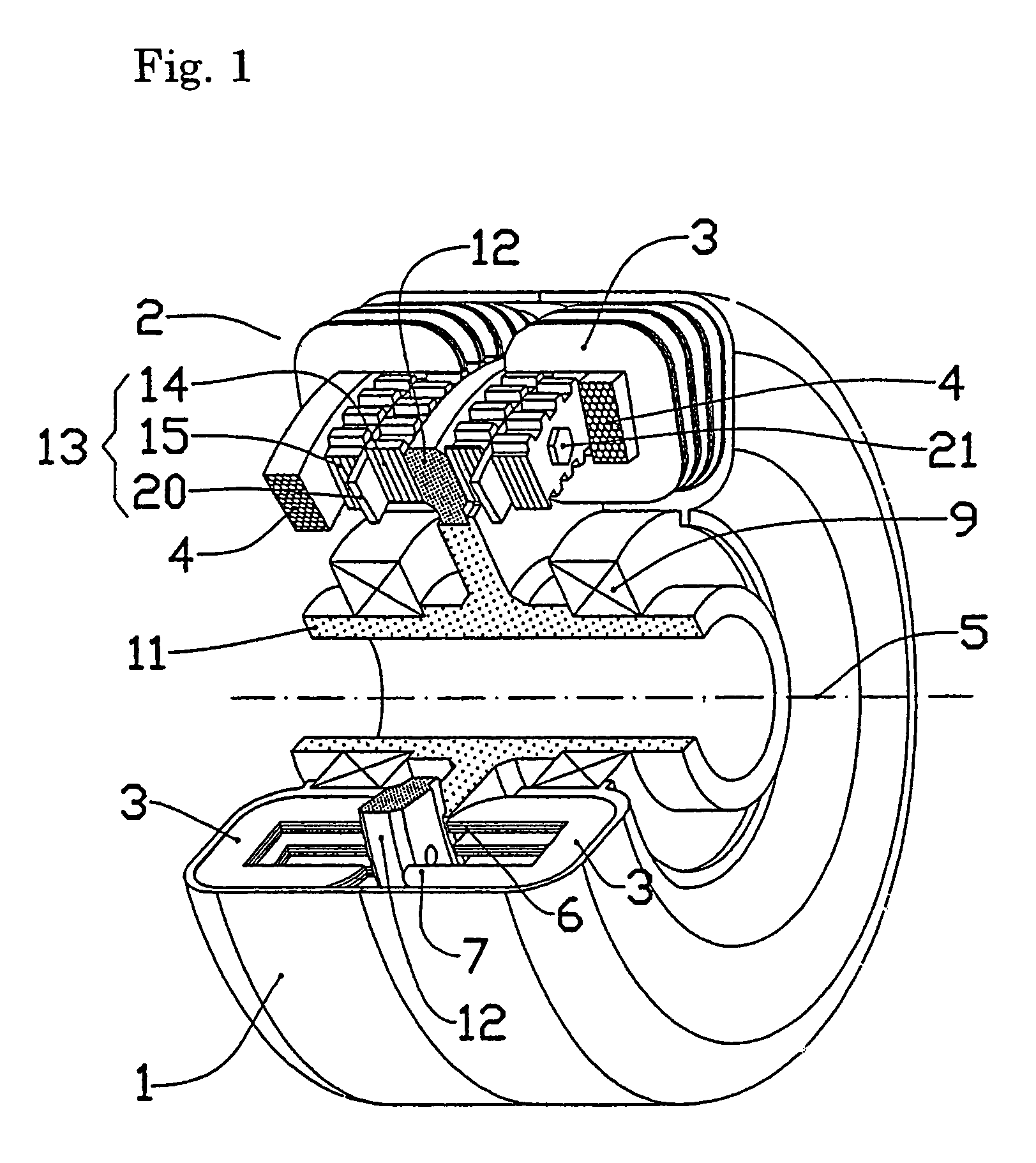
[0042]The rotor armature (11) connected to the stator armature (1) via ball bearings (9), is fitted with a massive copper ring (12) to which on each side an assembly (13) of rotor rings is fixed. This assembly (13), which is more precisely shown in FIG. 2(A) (example A), consists of two cogged rings (14, 15) of ...


PUM


Abstract

A hybrid synchronous electric machine driven by the transverse magnetic flux has a rotor and a stator, the rotor armature has a massive cogged iron rings (12) in close vicinity of active parts of the motor, and cogged iron rings (14, 15) as component parts of the rotor are provided with cross-cut insulating gaps. Eddy current losses are low because eddy currents in cogged iron rings are impeded by cross-cut insulating gaps therein. Eddy currents in all passive parts of the motor (rotor armature (11), stator armature (1), ball bearing (9) and the like) are negligible since the current induced in the copper ring (12) neutralizes all the dissipated magnetic flux outside the active area of the motor. A hybrid synchronous electric machine which has low eddy current losses and high energy efficiency can be realized.

Description

TECHNICAL FIELD[0001]The present invention pertains to a synchronous hybrid electric machine with transverse magnetic flux. In particular, the present relates to a synchronous hybrid electric machine whose structure is such that it minimizes eddy current losses in the motor and thus, it provides improved energy efficiency as compared to conventional motors with similar construction.PRIOR ART[0002]Hybrid electric machines are a subclass of synchronous electric machines. In construction they are similar to stepper motors with in-built permanent magnets that increase magnetic filed density in the air gap, but unlikely the stepper motors, the hybrid electric machines are usually fed by sinusoidal electric currents.[0003]Special constructions of such motors are already known. Namely, hybrid electric machines with transverse magnetic flux have coils, which are coaxial with the motor axis; their advantage is good energy efficiency due to small ohmic losses in the coaxial coils.[0004]A moto...

Claims


Application Information

Patent Timeline
Patent Type & Authority Patents(United States)
IPC IPC(8): H02K19/00H02K5/173H02K19/06H02K19/14H02K21/12
CPCH02K11/0005H02K21/125H02K5/1732H02K1/141H02K1/145H02K2201/12H02K11/0141
Inventor DETELA, ANDREJ
Owner HARMONIC DRIVE SYST IND CO LTD
Why Eureka
Try Eureka