Laminate Stack Comprising Individual Soft Magnetic Sheets, Electromagnetic Actuator, Process for Their Manufacture and Use of a Soft Magnetic Laminate Stack

a technology of electromagnetic actuator and laminate stack, which is applied in the direction of lamination, magnetic materials, printing, etc., can solve the problems of only achieving the cancellation of eddy current, affecting the quality of laminate stack, so as to reduce eddy current, reduce eddy current, and minimise the effect of loss

Inactive Publication Date: 2012-02-16
VACUUMSCHMELZE GMBH & CO KG
View PDF8 Cites 0 Cited by
  • Summary
  • Abstract
  • Description
  • Claims
  • Application Information

AI Technical Summary

Benefits of technology

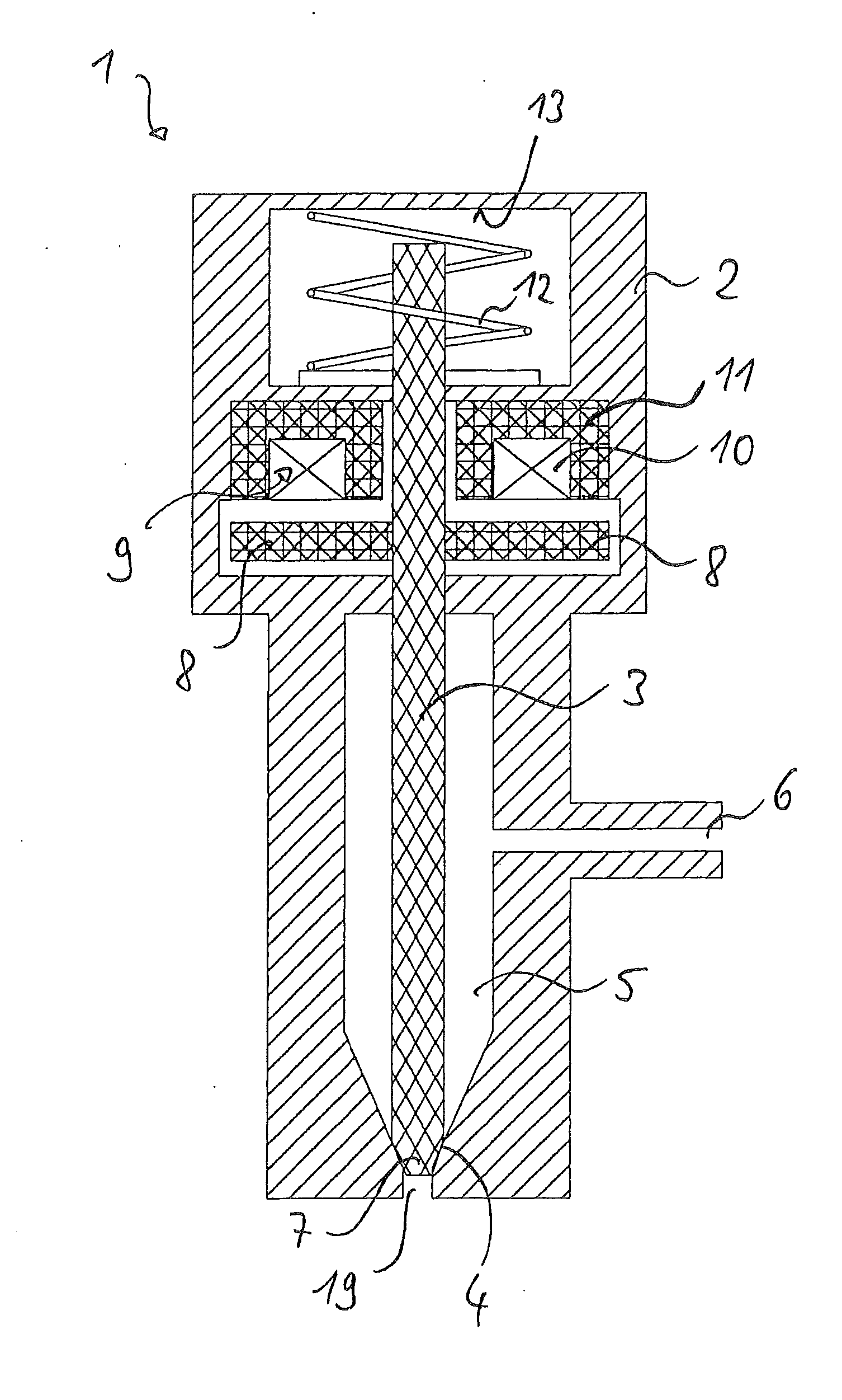
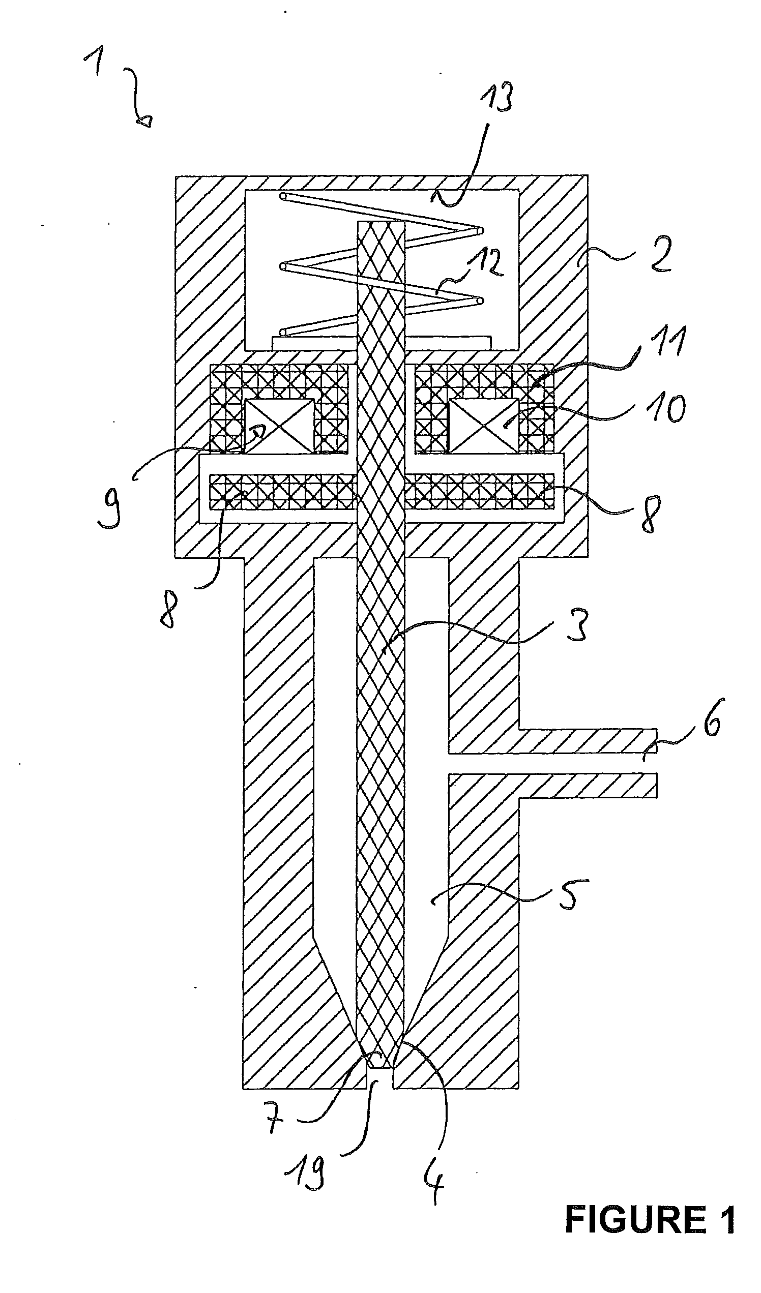
[0016]Due to the particular geometrical arrangement of the rectangular recess and the special dimensions of the individual sheets, respectively, embodiments of the laminate stack disclosed herein have significantly improved magnetic properties.
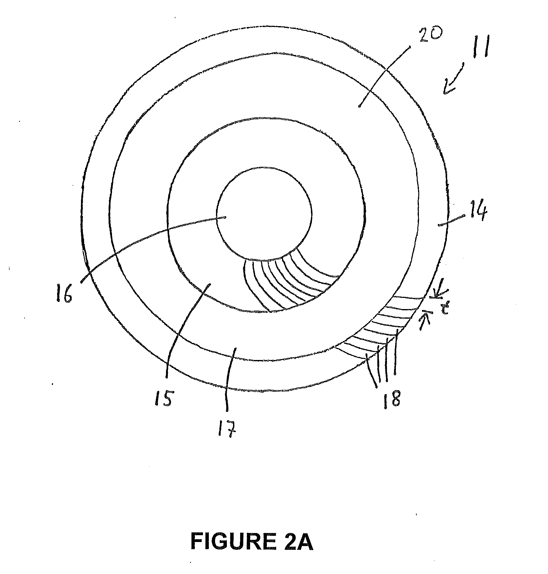
[0103]A composition of the soft magnetic core having sheet-type structures is particularly suitable for reducing eddy currents. However, in order to benefit from the advantages of these sheet-type structures, the magnetic flux should be able to run along the individual sheets when the injection valve is in operation and cross as few individual sheets as possible. Crossing more than a few individual sheets would result in considerable losses. Particularly preferred is the manufacture of individual sheets of constant thickness. Due to their involute arrangement for providing a laminate stack they can be used to build a radially symmetrical core in which the magnetic flux is able to run essentially parallel to the sheet plane, thereby minimising the losses. Due to this laminate stack design the magnet core also has particularly low eddy current losses.
[0105]Thus it becomes possible using a laminate stack as described herein to decouple the saturation polarisation and electrical resistance variables and so to obtain a magnet core which has high values for both variables. With a magnet core of this type it is possible to achieve both short injection valve switching times on one hand and low magnetisation switching losses and high retention forces on the other. The injection valve is therefore particularly suitable for direct injection in motor vehicles for which high retention forces are required due to the high fuel pressure and short switching times that are required to ensure economic operation.

Problems solved by technology

An important factor limiting the lower end of the time delay range is the occurrence of eddy currents induced in the electrically conductive bodies of the magnet armature by the time change in the magnetic field.
The disadvantages of this arrangement are that this cancelling out of eddy currents can only be achieved locally and that the magnetic flux is also cancelled out.
However, losses due to eddy currents remain high and prevent fast switching times. In addition, the constraints placed on the geometry of the coils and pole bodies in achieving maximum cancelling out of the eddy currents severely limit the design of the injection valve.
However, this injection valve has several disadvantages.
In such arrangements, moreover, the flux is required to flow parallel to the sheet normal and radially in relation to the concentric rings, respectively, and to pass across a gap between two sheets or rings, producing undesirably low permeability values for the system as a whole.
For t*≧π it is no longer possible simply to place the individual sheets one on top of another.
Crossing more than a few individual sheets would result in considerable losses.
Alloys with high saturation polarisation generally simultaneously present the disadvantage of low electrical specific resistance and thus favour the occurrence of eddy currents.

Method used


Image

  • Laminate Stack Comprising Individual Soft Magnetic Sheets, Electromagnetic Actuator, Process for Their Manufacture and Use of a Soft Magnetic Laminate Stack
  • Laminate Stack Comprising Individual Soft Magnetic Sheets, Electromagnetic Actuator, Process for Their Manufacture and Use of a Soft Magnetic Laminate Stack
  • Laminate Stack Comprising Individual Soft Magnetic Sheets, Electromagnetic Actuator, Process for Their Manufacture and Use of a Soft Magnetic Laminate Stack

Examples


Embodiment Construction

[0122]In one embodiment the alloy of the individual sheets may consist essentially of:[0123]12.0 percent by weight≦Co≦22.0 percent by weight,[0124]1.5 percent by weight≦Cr≦4.0 percent by weight,[0125]0.4 percent by weight≦Mo≦1.2 percent by weight,[0126]0.1 percent by weight≦V≦0.4 percent by weight,[0127]0.05 percent by weight≦Si≦0.15 percent by weight,

and the remainder Fe.

[0128]In particular, the alloy of the individual sheets may consist essentially of 17.0 percent by weight Co, 2.2 percent by weight Cr, 0.8 percent by weight Mo, 0.2 percent by weight V, 0.09 percent by weight Si and the remainder Fe.

[0129]In a further embodiment the alloy of the individual sheets may consist essentially of:[0130]12.0 percent by weight≦Co≦22.0 percent by weight,[0131]1.5 percent by weight≦Cr≦4.0 percent by weight,[0132]1.0 percent by weight≦Mn≦1.8 percent by weight,[0133]0.4 percent by weight≦Si≦1.2 percent by weight,[0134]0.1 percent by weight≦A≦10.4 percent by weight,

and the remainder Fe.

[0135]In...


PUM

PropertyMeasurementUnit
soft magneticaaaaaaaaaa
thicknessaaaaaaaaaa
inside radius Diaaaaaaaaaa

Abstract

A laminate stack having individual soft magnetic sheets. The individual sheets are involutely curved in the laminate stack. Each individual sheet has a first long side, a second long side opposite the first long side, a first short side and a second short side opposite the first short side. The first long side has a recess, said recess being rectangular and equidistant from the first short side, the second short side and the second long side when the individual sheet is in its uncurved state.

Description

BACKGROUND[0001]1. Field[0002]Disclosed herein is a laminate stack comprising individual soft magnetic sheets, an electromagnetic actuator for controlling a quantity of fuel to be fed into an internal combustion engine for example, and a process for their manufacture.[0003]2. Description of Related Art[0004]An electromagnetic actuator comprises a valve seat with a fitting valve body, it being possible to move the valve body by means of a magnetic field acting on a magnet armature connected to the valve body. In this arrangement the magnetic field is built up by passing a current through a coil, the magnetic flux penetrating the magnet armature with a time delay.[0005]Short switching times of less than 40 μs to 100 μs are desirable, particularly in electromagnetic actuators used as injection valves. In order to achieve short valve switching times, the time delay between the passing of the current through the coil and the build up of the magnetic field in the magnet armature should be...

Claims


Application Information

Patent Timeline
Patent Type & Authority Applications(United States)
IPC IPC(8): H01F7/16B32B15/18H01F3/02B32B15/04C25D7/00B32B3/10B29C65/00B32B1/00
CPCF02M51/0653H01F1/147H01F1/14716H01F3/02H01F7/1638H01F27/2455H01F41/024H01F2007/1676Y10T428/24612Y10T428/24322Y10T428/12389Y10T156/10F02M51/0614H01F7/11
Inventor GERSTER, JOACHIMHOEHN, HERBERT
Owner VACUUMSCHMELZE GMBH & CO KG
Why Eureka
Try Eureka