
Display unit and method of manufacturing the same

a technology of display unit and manufacturing method, which is applied in the direction of discharge tube luminescnet screen, door/window protection device, gas-filled discharge tube, etc., can solve the problems of degradation of organic light-emitting device, and achieve the effect of external moisture and high reliability

Active Publication Date: 2006-04-25
JOLED INC
View PDF8 Cites 20 Cited by
  • Summary
  • Abstract
  • Description
  • Claims
  • Application Information

AI Technical Summary

Benefits of technology

[0009]In an embodiment, the present invention provides a display unit capable of preventing the entry of moisture via a coating layer and having higher reliability, and a method of manufacturing the display unit.
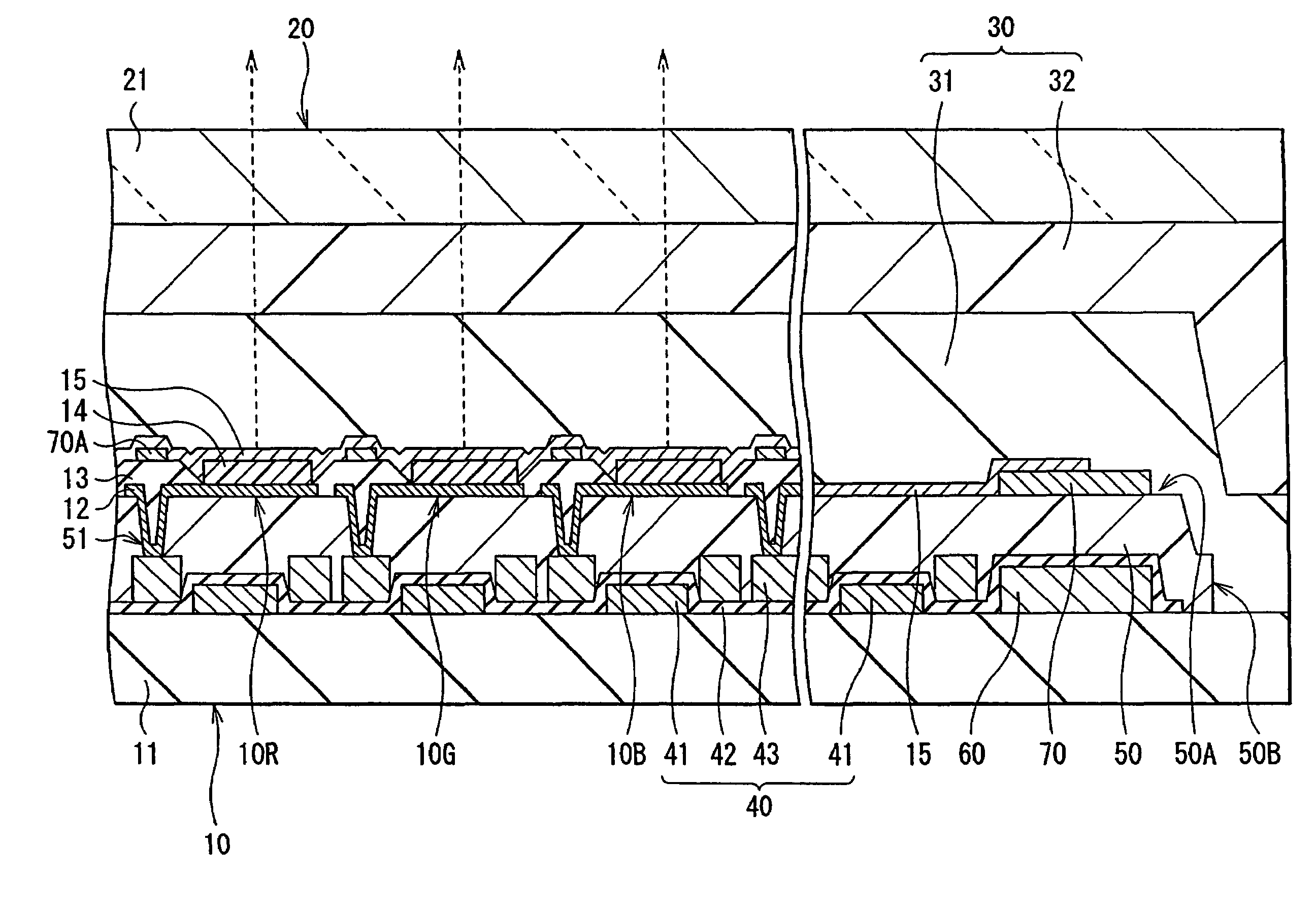
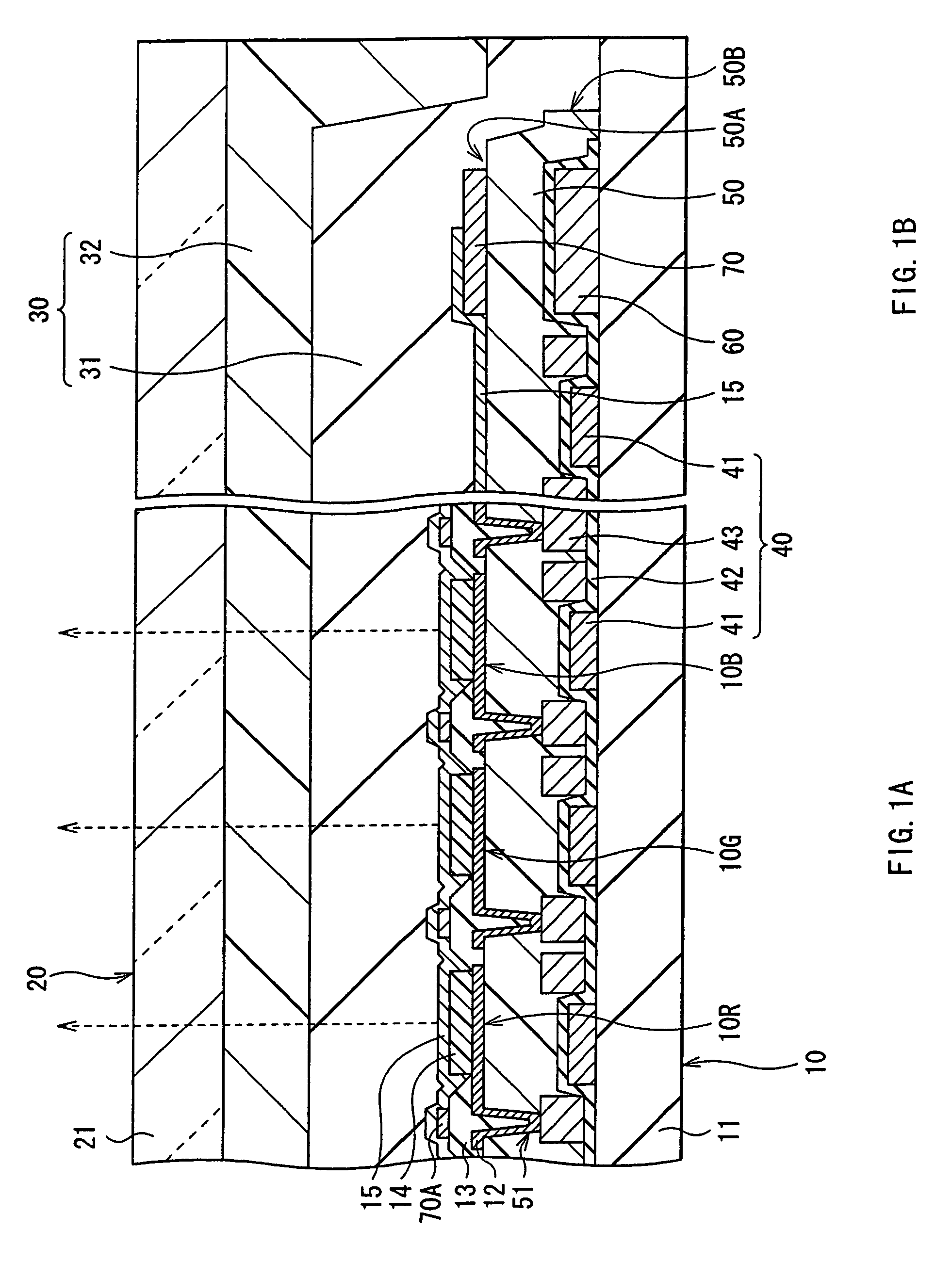
[0012]In the display unit according to an embodiment of the invention, the middle layer is laid over not only the surface but also the end surface of the coating layer, so the end surface of the coating layer is not exposed to outside from between the drive panel and the sealing panel, thereby external moisture can be prevented from entering a light-emitting device portion via the coating layer.
[0014]In an embodiment, a display unit is provided that is capable of preventing the entry of moisture via a coating layer and having higher reliability. A drive panel and a sealing panel face each other with a middle layer in between. The drive panel includes organic light-emitting devices on a drive substrate with a drive device layer and a coating layer being laid over the drive device layer in between. The middle layer is disposed between the drive panel and the sealing panel so as to be laid over the organic light-emitting devices, and the middle layer is laid over not only a surface but also an end surface of the coating layer, Therefore, the end surface of the coating layer is not exposed froze between the drive panel and the sealing panel, so external moisture can be prevented from entering via the coating layer.

Problems solved by technology

Therefore, external moisture may enter via the coating layer as a path, thereby resulting in degradation of the organic light-emitting devices.

Method used


Image

  • Display unit and method of manufacturing the same
  • Display unit and method of manufacturing the same
  • Display unit and method of manufacturing the same

Examples


Embodiment Construction

[0028]The present invention generally relates to a display unit. More specifically, the present invention relates to a display unit in which a device panel that includes a light-emitting device and a sealing panel that face each other with a middle layer in between and a method of manufacturing same. In an embodiment, the present invention provides a display unit suitable for an organic light-emitting display that uses a top emission organic light-emitting device and methods of manufacturing same.

[0029]Preferred embodiments of the invention will be described in more detail below referring to the accompanying drawings.

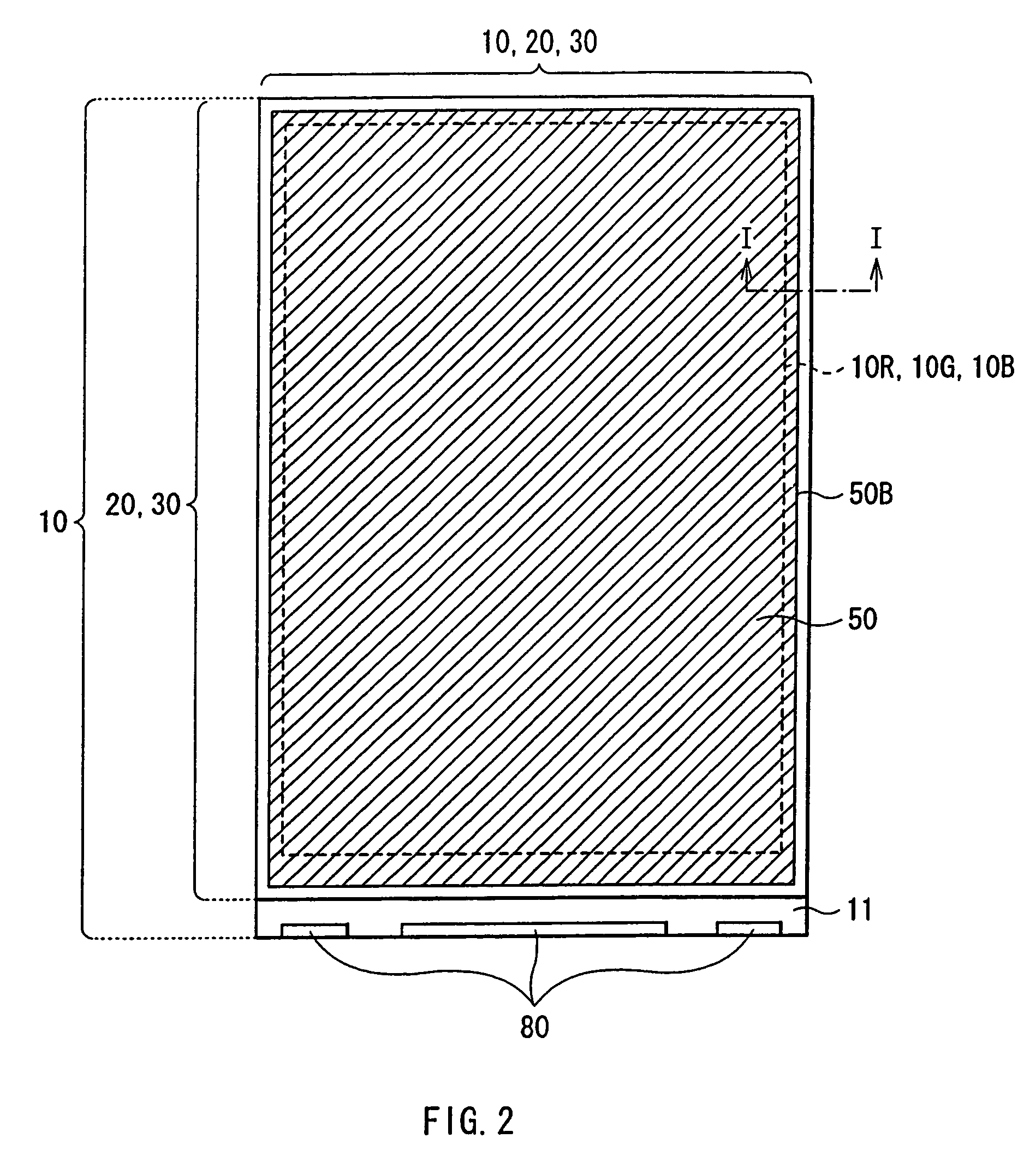
[0030]FIGS. 1A and 1B show sectional views of a display unit according to an embodiment of the invention. The display unit is used as an ultra-thin organic light-emitting display, for example, and in the display unit, a drive panel 10 and a sealing panel 20 face each other, and a middle layer 30 is disposed between the drive panel 10 and the sealing panel 20. In the dri...


PUM


Abstract

A display unit and method of manufacturing same is provided. The display unit includes a drive panel and a sealing panel that face each other with a middle layer in between. The display panel includes a number of light-emitting devices on a drive substrate with a drive device layer and a coating layer that is provided over the drive device layer in between. The middle layer is disposed between the drive panel and the sealing panel so as to be laid over the light-emitting devices.

Description

CROSS REFERENCE TO RELATED APPLICATIONS[0001]The present invention claims priority to Japanese Patent Document Nos. P2003-046318 filed on Feb. 24, 2003, and P2004-010345 filed on Jan. 19, 2004, the disclosures of which are herein incorporated by reference.BACKGROUND OF THE INVENTION[0002]The present invention relates to a display unit in which a drive panel including a light-emitting device and a sealing panel face each other with a middle layer in between, and a method of manufacturing the display unit, and more specifically to a display unit suitable for an organic light-emitting display using a top emission organic light-emitting device, and a method of manufacturing the display unit.[0003]In recent years, organic light-emitting displays using an organic light-emitting device as an alternative to liquid crystal displays have become a focus of attention. The organic light-emitting displays are of a self-luminous type, so it is considered that the organic light-emitting displays ha...

Claims


Application Information

Patent Timeline
IPC IPC(8): H05B33/00H05B33/04H01J17/00H01L27/32H01L51/50H01L51/52H01S3/08H05B33/10H05B33/14H05B33/26
CPCH01L51/5237H01L27/3244H10K59/12H10K59/8722H10K59/873E06B9/262E06B2009/2622E06B2009/785H10K50/844H10K50/8426
Inventor IWASE, YUICHIASANO, MITSURUHIRANO, TAKASHI
Owner JOLED INC
Learn More