Multi-phase buck converter

a multi-phase buck converter and converter technology, applied in the direction of electric variable regulation, process and machine control, instruments, etc., can solve the problems of damage to the circuitry connected to the output, the conventional multi-phase buck converter does not provide a robust architecture capable of easy expansion, and the conventional multi-phase buck converter does not optimally control the output voltage. , to achieve the effect of efficient and simpl

Inactive Publication Date: 2006-04-25
INFINEON TECH AMERICAS CORP
View PDF7 Cites 37 Cited by
  • Summary
  • Abstract
  • Description
  • Claims
  • Application Information

AI Technical Summary

Benefits of technology

[0011]By separating the functions of the phase control arrangement and the phase output arrangements, an exemplary multi-phase buck converter according to the present invention contains no unused or redundant silicon, since the buck converter may include only those number of phase output arrangements required for a particular application. Thus, if a design engineer requires, for example, a three-phase buck converter for a particular application, the engineer may design the multi-phase buck converter to include only three phase output arrangements, each of which is assigned to a respective one of the three phase outputs. Furthermore, the phase control bus (e.g., a 5-wire analog bus) permits the multi-phase buck converter of the present invention to communicate with a potentially unlimited number of phase output arrangements, without requiring point-to-point electrical connections between the phase control arrangement and each of the phase output arrangements. In this manner, the multi-phase buck converter permits an efficient and easily scalable phase architecture.
[0013]In accordance with yet another exemplary embodiment of the present invention, each of the output phase arrangements operates to switch off both the high-side and low-side switches in response to a request for a lower desired output voltage (VDES) or a decrease in current demand of the load. In this manner, the slew rate of the inductor is increased, which enhances the response time of the multi-phase buck converter of the present invention and prevents disadvantageous negative currents from flowing through the output inductor and possibly damaging the power supply.
[0015]By connecting resistor RCS and capacitor CCS across the nodes of the output inductor, the current flowing through the output inductor 220 may be sensed by selecting resistor RCS and capacitor CCS such that the time constant of resistor RCS and capacitor CCS equals the time constant of the output inductor 220 and its DC resistance (i.e., inductance L / inductor DCR, where DCR is the inductor DC resistance), the voltage across capacitor. In this manner, this embodiment of the present invention permits each of the output phase arrangements to sense the current provided to the load in a lossless manner (i.e., without interfering with the current provided to the load).
[0016]In accordance with yet another exemplary embodiment of the present invention, the phase control arrangement includes droop circuitry configured to reduce the output voltage in proportion to the current demand of the load. In this manner, this exemplary embodiment permits an efficient and simple method to adaptively modify the output voltage via adaptive voltage positioning.

Problems solved by technology

. . , 2005n, conventional multi-phase buck converters do not provide a robust architecture capable of easy expandability to include any number of desired phases.
Furthermore, conventional multi-phase buck converters do not optimally control the output voltage in response to a request for a lower desired output voltage or a decrease in current demand of the load 1935.
By not optimally controlling the output voltage, conventional multi-phase buck converters may produce unwanted voltage spikes, which may damage circuitry connected to the output of the buck converter.

Method used


Image

  • Multi-phase buck converter
  • Multi-phase buck converter
  • Multi-phase buck converter

Examples


Embodiment Construction

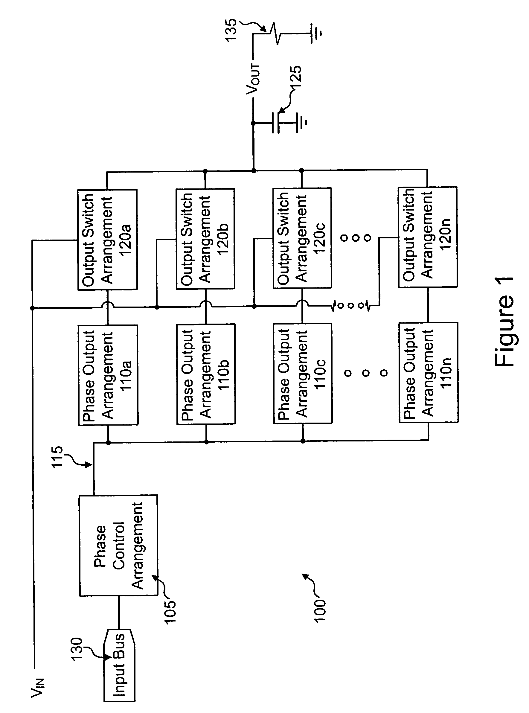
[0042]Referring now to FIG. 1, there is seen a first exemplary multi-phase buck converter 100 according to the present invention. Buck converter 100 includes phase control arrangement 105 electrically and communicatively coupled to input bus 130, phase output arrangements 110a, 110b, 110c, . . . , 110n electrically and communicatively coupled to the phase control arrangement 105 via a phase control bus 115 (e.g., a 5-wire analog bus), output switch arrangements 120a, 120b, 120c, . . . , 120n electrically and communicatively coupled to an input voltage (VIN) and phase output arrangements 110a, 110b, 110c, . . . , 110n, an output capacitor 125 electrically coupled to the output switch arrangements 120a, 120b, 120c, . . . , 120n for producing an output voltage (VOUT), and a load 135 electrically connected between the output voltage (VOUT) and ground.

[0043]The exemplary multi-phase buck converter 100 of FIG. 1 may be used, for example, in applications requiring small sizes, design flexi...


PUM


Abstract

A buck converter for providing an output voltage to a load, including a plurality of output switch arrangements having respective output inductors coupled to an output capacitor, the switch arrangements being controllable to provide phase output currents to the output capacitor; a plurality of phase output arrangements respectively coupled to the output switch arrangements, the phase output arrangements being controllable to set the respective phase output currents supplied by the output switch arrangements; a phase control bus communicatively coupled to each of the phase output arrangements; and a phase control arrangement communicatively coupled to the phase control bus, the phase control arrangement being configured to control the phase output arrangements to set the respective phase output currents so that the output voltage approximates the desired voltage; wherein the phase control arrangement and the phase output arrangements are provided as respective integrated circuits.

Description

RELATED APPLICATIONS[0001]The present Application is a continuation application of U.S. patent application Ser. No. 10 / 392,121, filed Mar. 18, 2003, now U.S. Pat. No. 6,806,689, entitled MULTI-PHASE BUCK CONVERTER, which application is based on and claims the benefit of U.S. Provisional Application No. 60 / 366,889, filed on Mar. 22, 2002, entitled SYNCHRONOUS BUCK CONVERTER WITH MULTIPLE PHASES, the entire contents of which are expressly incorporated herein by reference.FIELD OF THE INVENTION[0002]The present invention relates to buck converters, such as multi-phase buck converters for use in low voltage / high-current applications.BACKGROUND INFORMATION[0003]Various applications may provide a conventional DC-to-DC buck converter that accepts a DC input voltage and produces a lower DC output voltage to drive at least one circuit component. Buck converters are typically used in low voltage applications requiring high amounts of load current (e.g., 30 amps or more). Typically, as shown i...

Claims


Application Information

Patent Timeline
Patent Type & Authority Patents(United States)
IPC IPC(8): G05F1/44H02M3/155H02M3/158
CPCH02M3/1584H02M3/1588Y02B70/1466H02M2003/1586H02M2001/0012H02M1/0012H02M3/1586Y02B70/10
Inventor SCHUELLEIN, GEORGECLAVETTE, DANCROWTHER, MARK
Owner INFINEON TECH AMERICAS CORP
Why Eureka
Try Eureka