
Printed dipole antenna

a dipole antenna and printed circuit board technology, applied in the direction of antennas, antenna feed intermediates, antenna details, etc., can solve the problems of not optimizing for the smallest printed circuit board real estate possible, not optimizing for maximum bandwidth,

Inactive Publication Date: 2006-04-25
AVAGO TECH WIRELESS IP SINGAPORE PTE
View PDF10 Cites 145 Cited by
  • Summary
  • Abstract
  • Description
  • Claims
  • Application Information

AI Technical Summary

Problems solved by technology

While the various types of antennas and corresponding shapes provide adequate antenna performance, they are not optimized to consume the smallest printed circuit board real estate possible nor are they optimized for maximum bandwidth.

Method used


Image

  • Printed dipole antenna
  • Printed dipole antenna
  • Printed dipole antenna

Examples


Embodiment Construction

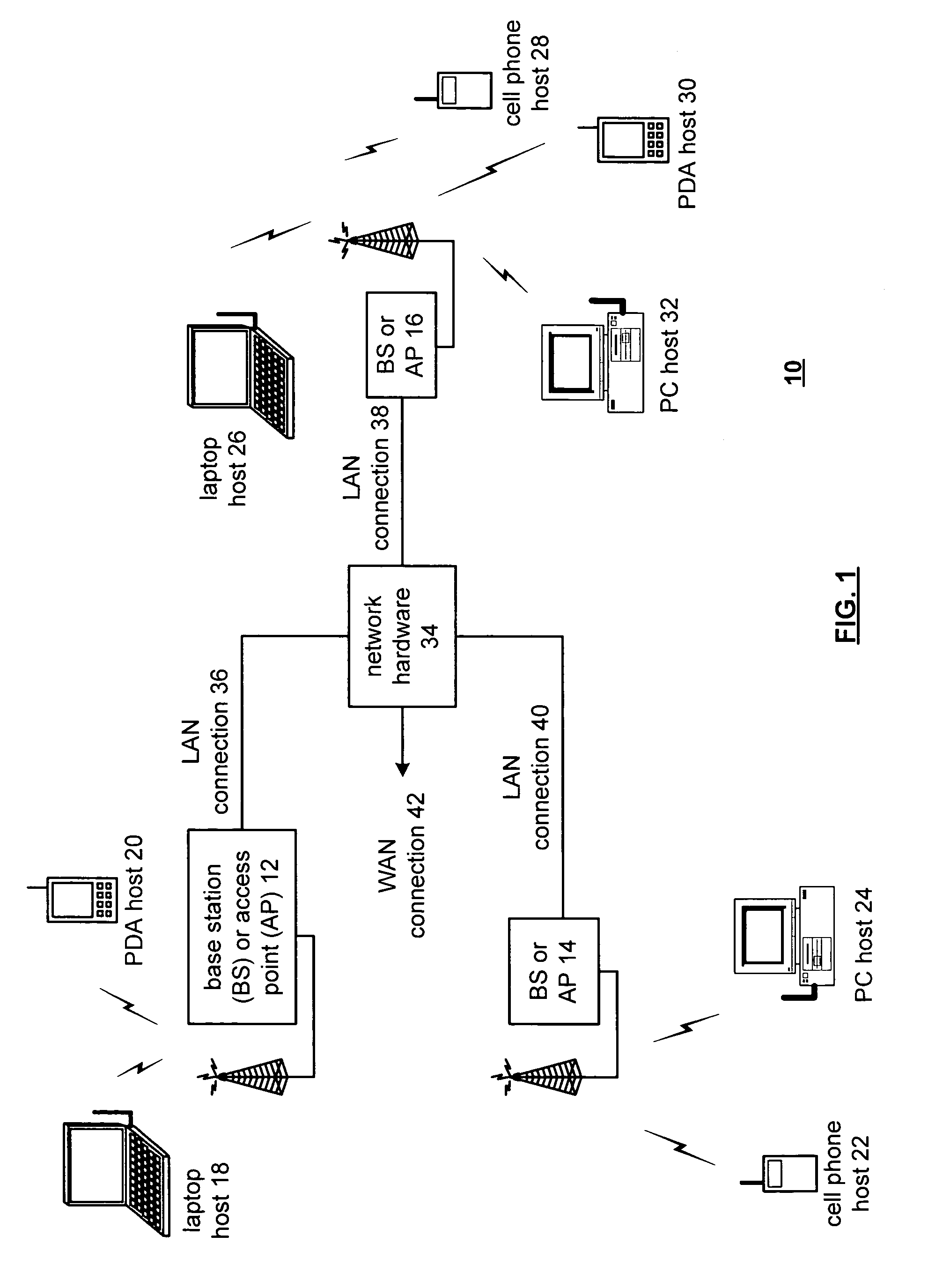
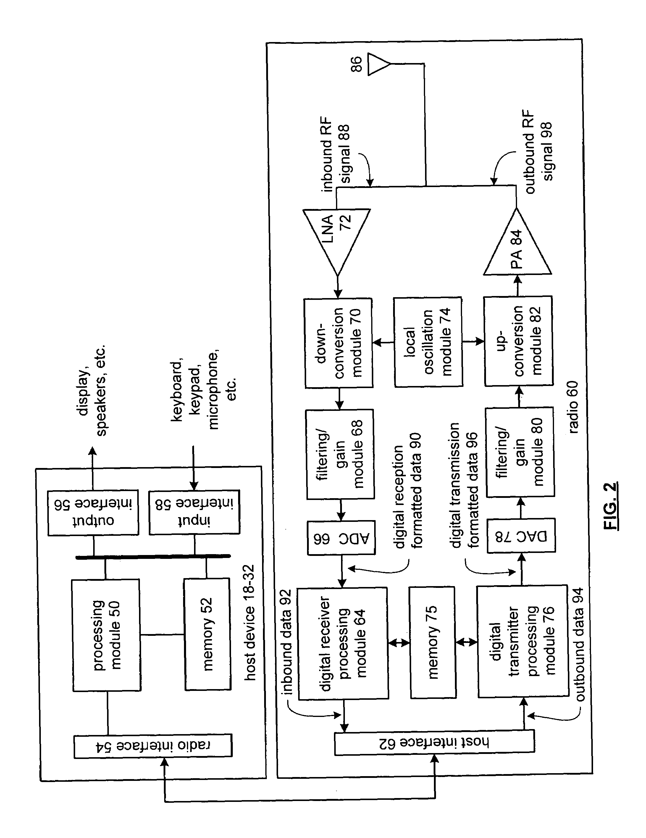
[0020]FIG. 1 illustrates a schematic block diagram of a communication system 10 that includes a plurality of base stations and / or access points 12–16, a plurality of wireless communication devices 18–32 and a network hardware component 34. The wireless communication devices 18–32 may be laptop host computers 18 and 26, personal digital assistant hosts 20 and 30, personal computer hosts 24 and 32 and / or cellular telephone hosts 22 and 28. The details of the wireless communication devices will be described in greater detail with reference to FIG. 2.

[0021]The base stations or access points 12 are operably coupled to the network hardware 34 via local area network connections 36, 38 and 40. The network hardware 34, which may be a router, switch, bridge, modem, system controller, et cetera provides a wide area network connection 42 for the communication system 10. Each of the base stations or access points 12–16 has an associated antenna or antenna array to communicate with the wireless c...


PUM


Abstract

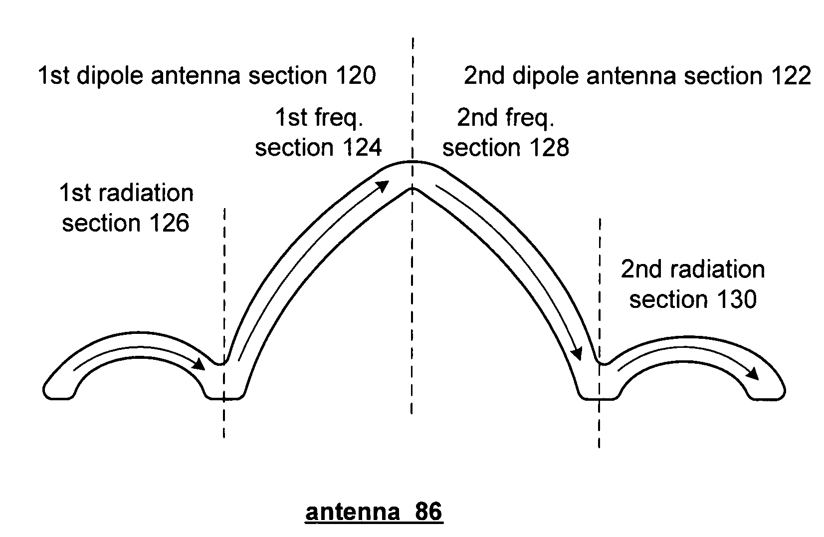
A printed dipole antenna includes a metal trace having first type sections and second type sections, wherein currents within the first type sections substantially cancel and currents the second type sections are substantially cumulative.

Description

[0001]This patent application is claiming priority under 35 USC § 120 to and is a continuation of co-pending patent application entitled PRINTED ANTENNA AND APPLICATIONS THEREOF, having a Ser. No. of 10 / 128,192, and a filing date of Apr. 23, 2002 now U.S. Pat. No. 6,753,825.TECHNICAL FIELD OF THE INVENTION[0002]This invention relates generally to wireless communications and more particularly to antennas used within such wireless communication systems.BACKGROUND OF THE INVENTION[0003]As is known, an antenna is an essential element for every wireless communication device regardless of what type of wireless communication system the device is used in. The antenna provides a wireless interface for the wireless communication device, which may be a radio, cellular telephone, pager, station (for wireless local area network, wireless internet, et cetera). The particular type of wireless communication system, which prescribes the transmission frequencies, reception frequencies and power level...

Claims


Application Information

Patent Timeline
IPC IPC(8): H01Q9/16H01Q1/38H01Q9/28
CPCH01Q9/285H01Q1/38
Inventor YANG, HUNG YU DAVIDCASTANEDA, JESUS A
Owner AVAGO TECH WIRELESS IP SINGAPORE PTE
Learn More