Router-assisted multicast congestion control

a multicast and congestion control technology, applied in the field of multicast transfer of packets, to achieve the effect of convenient and expandable methods

Inactive Publication Date: 2006-04-25
CISCO TECH INC
View PDF17 Cites 67 Cited by
  • Summary
  • Abstract
  • Description
  • Claims
  • Application Information

AI Technical Summary

Benefits of technology

[0013]The invention provides a convenient and expandable method for transmitting one or more loss rate statistics determined in a distributed manner from a multicast distribution tree to a source computer of the multicast distribution. First, the loss rate statistics are collected in a distributed manner from target receiver stations, and from routers in the multicast distribution tree. Second, there is a distributed calculation of loss rate statistics rate by routers in the multicast distribution tree. Third, there is transportation of the loss rate statistics back to the source computer in reverse along the multicast distribution tree. The source computer is then informed of loss rate statistics from all parts of the multicast distribution tree, including any bottleneck links in the multicast distribution tree.

Problems solved by technology

Third, there is transportation of the loss rate statistics back to the source computer in reverse along the multicast distribution tree.

Method used


Image

  • Router-assisted multicast congestion control
  • Router-assisted multicast congestion control
  • Router-assisted multicast congestion control

Examples


first exemplary embodiment

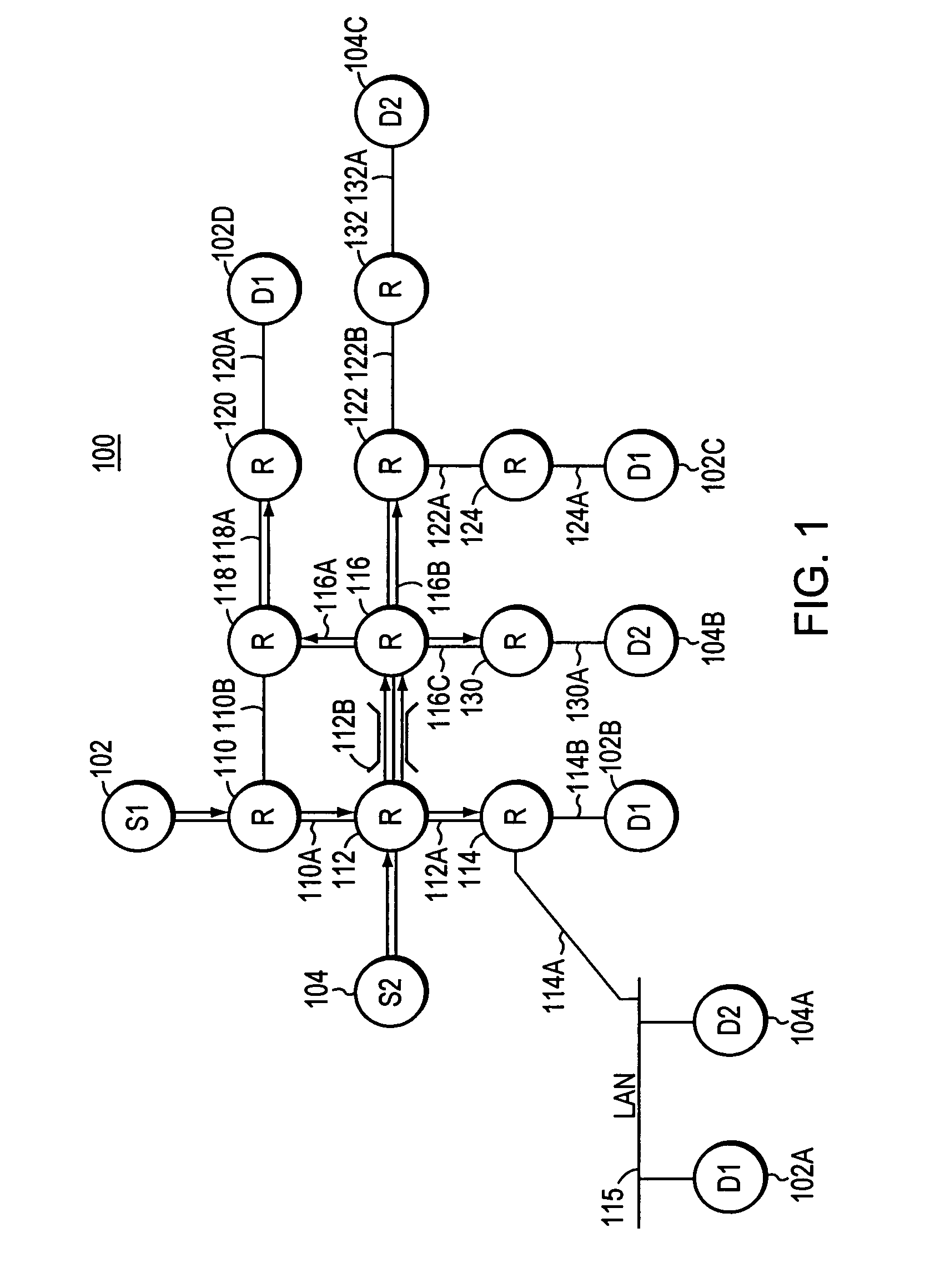
[0024]Turning now to FIG. 1, computer network 100 is shown. For the purpose of this discussion, source stations are indicated by “S”, routers are indicated by “R”, and destination stations are indicated by “D”. Destination stations may also become source stations, etc., and for the purpose of this discussion only, the stations have the indicated roles.

[0025]Source station 102 and source station 104 both are transmitting data packets onto computer network 100. For the purpose of this discussion, both source station 102 and source station 104 are sources of multicast group data packets.

[0026]Source station 102 transmits multicast group packets to the group of stations comprising destination stations marked as group “D1”, for example destination stations 102A, 102B, 102C, 102D, etc. These packets are referred to as group D1 multicast group data packets.

[0027]Further, source station 104 transmits multicast group packets to the group of stations comprising destination stations marked as ...

second exemplary embodiment

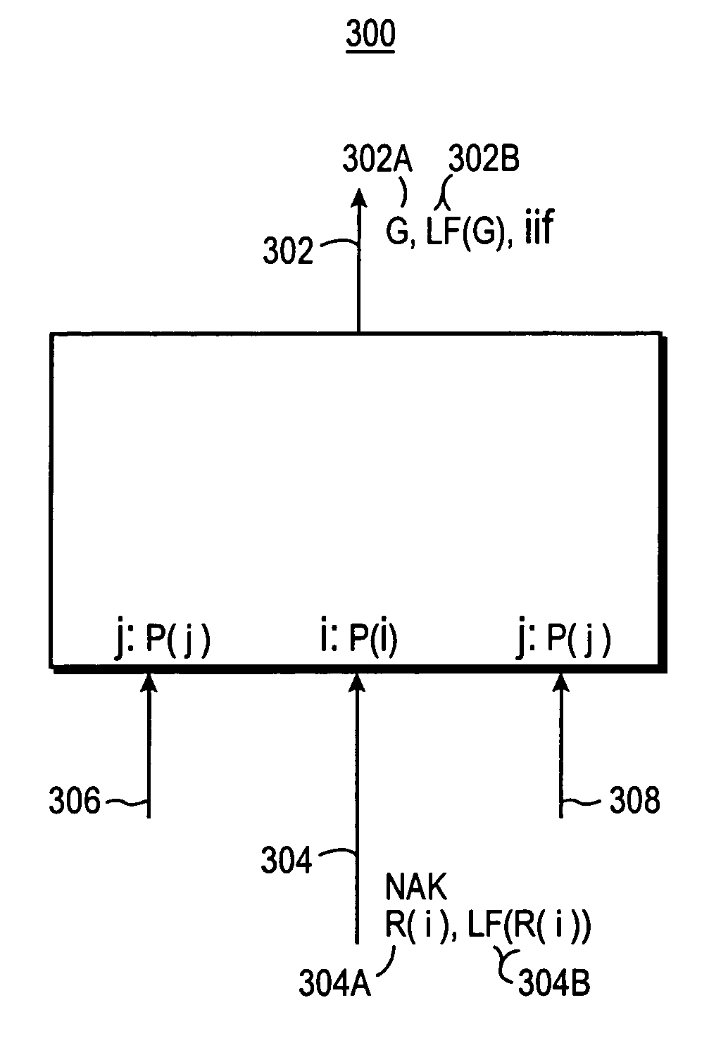
[0126]In the FIRST EXEMPLARY EMBODIMENT of the invention, the loss report is carried by a NAK message in reverse up the multicast distribution tree. Alternatively, a generalized loss report message may be used to carry the loss rate from a receiver station to a source station.

[0127]For example, receivers may periodically transmit a loss report message up the multicast distribution tree, rather than wait for receipt of a NAK from a receiver station. Such a loss report message is referred to as a “unsolicited periodic loss report”. An advantage to using an unsolicited periodic loss report is that the periodicity of the message may be used by the multicast system as an indication that the receiver station remains an active receiver station.

third exemplary embodiment

[0128]In the FIRST EXEMPLARY EMBODIMENT of the invention, the computation of the loss rate by a router computes the worst loss rate reported from any of the links connected to the router. The computed loss rate is then forwarded upstream in a loss rate report to the next upstream router. Alternatively, other computational methods may be utilized to compute the loss rate to be forwarded upstream by a router.

[0129]For example, a loss rate at a port of the router may be computed by adding the loss rate received in a loss rate report at the port (LP[received]) to the loss rate measured by the router at that port (LP[measured]). For example, then the largest computed loss rate at any port (in the multicast distribution tree) of the router is written into the loss rate report transmitted upstream to the next higher router in the multicast distribution tree.

[0130]Alternatively, any convenient computational scheme which measures the loss rate experienced by the router, based on received and...


PUM


Abstract

The invention provides a convenient and expandable method for transmitting one or more loss rate statistics determined in a distributed manner from a multicast distribution tree to a source computer. First, the loss rate statistics are collected in a distributed manner from target receiver stations, and from routers in the multicast distribution tree. Second, there is a distributed calculation of statistics on loss rate by routers in the multicast distribution tree. Third, there is transportation of the loss rate statistics back to the source computer in reverse along the multicast distribution tree. For example, congestion information is collected by routers, and the congestion information is sent upstream to the multicast source station in fields of NAK messages. A router may receive a NAK packet in transit from an intended destination station to a source station, the NAK packet indicating loss of a data packet. The router writes a loss rate statistic determined by the router into a “loss rate field” of a message to be sent upstream along the reverse of the distribution tree. The router determines the loss rate statistic to be written into the loss rate field of the message, in response to: analyzing the loss rate statistics on each of its links; the loss rate reported by the incoming NAK packet; and, the elapsed time from the time stamp showing when the various loss rate statistics were determined.

Description

FIELD OF THE INVENTION[0001]This invention relates to multicast transfer of packets over a computer network, and more particularly to control of congestion in intermediate links of the computer network during multicast transfer.BACKGROUND OF THE INVENTION[0002]Modern computer networks often have many routers interconnected, and the routers route multicast packets from at least one source station to multiple destination stations. Additionally, the routers route ordinary data traffic in the computer network, and may route many different multicast sessions, each session originating from a different source station. Links of the network between routers may become congested from the traffic load which they are required to carry. When a link becomes congested, the packets may be discarded by a router, that is, the router may simply drop the packet rather than transmit it.[0003]Congestion of a link is often caused by a transmitting queue in a transmitting router which sends packets to the l...

Claims


Application Information

Patent Timeline
Patent Type & Authority Patents(United States)
IPC IPC(8): G01R31/08H04L1/00
CPCH04L1/1671
Inventor VICISANO, LORENZOSPEAKMAN, TONY
Owner CISCO TECH INC
Why Eureka
Try Eureka