Fixing piece for a windscreen wiper

a technology for windscreen wipers and fixing parts, which is applied in vehicle maintenance, vehicle cleaning, cleaning equipment, etc., can solve problems such as contact corrosion in the interconnecting region, and achieve the effect of reducing production time and cos

Inactive Publication Date: 2006-05-02
ROBERT BOSCH GMBH
View PDF19 Cites 32 Cited by
  • Summary
  • Abstract
  • Description
  • Claims
  • Application Information

AI Technical Summary

Benefits of technology

[0005]In accordance with the present invention, the spring mount of a mounting part designed as a sheet metal bent component is formed from a sidewall of the u-shaped cross-section profile by deep-drawing. Thus, the sheet metal form part is designed as one piece and includes all the essential functional elements, such as a receiving opening for a wiper shaft, a part of a fold-away hinge and a spring mount for an extension spring. In order to avoid subsequent assembly steps, as many functions as possible are integrated in one component, which reduces production time and cost. Furthermore, there is no contact corrosion in a one-piece mounting part, since there are no critical connecting regions, at riveting pins, for instance.
[0006]For better bracing or introduction of the spring forces in the sidewall of the u-profile, the deep-drawn spring mount has a conical shape that widens in the direction of the sidewall. As a result, the spring mount has a sturdy design, resulting in minimal elastic deformation in response to forces, and, in this manner, minimizing, or entirely eliminating, the effect on the application force of the wiper blade.
[0007]The spring mount has a round cross-section. It may also be oval, in which case it is expedient for the larger diameter to point in the direction of the force of the extension spring when the wiper arm is in the working position. The cross-section of the spring mount narrows from the sidewall to a necking, and then widens again from that point to the free end. Furthermore, the necking contour is adapted to the cross-section contour of a c-shaped retaining clip, so that the extension spring is securely fastened and will not slide off the mounting in response to vibrations. A lateral stop is required to anchor the extension spring. This is created in a simple manner by compressing the free end of the spring mount or, in a variant of the present invention, by punching and subsequent widening of the end region.
[0008]In order to reduce the friction between the spring mount and the c-shaped clip and thereby the wear resulting from the slight rotation of the c-clip during operation, the necking region is expediently provided with a coating of a bearing material, such as plastic, or an additional plastic ring. In this manner, the wiper arm can be folded back from the vehicle windshield more easily. The spring mount is preferably deep-drawn from only one sidewall of the u-profile and projects into the u-shaped cross-section profile, up to its center region. In this manner, a clearance is created adjacent to the spring mount, in which, for instance, the tube leading to the water supply of a windshield washer system could be accommodated. Due to the deep-drawn spring mount, a visible insertion point is present on the side of the mounting part, located in a region that is either covered by the articulated part or possibly by a protective cover. In this context, it is advantageous if the spring mount originates from a downward-pointing sidewall of the mounting part, for instance pointing towards the vehicle hood, in order to prevent dirt and water from accumulating in the hollow space of the spring mount which is open to the outside.
[0009]In accordance with the present invention, the spring mount is produced in several drawing steps. The material is first drawn in over a large area, so that a uniform wall thickness across all regions is achieved. The conical region is then formed in several steps and a cylindrical region at the closed end, as well as the end piece formed as a stop. Since the receiving opening for the wiper shaft is deep-drawn like the spring mount, both regions may be produced using one tool, in particular since the production of both regions requires approximately the same number of drawing steps (approx. 5 to 7). While this may slightly increase the cost of the deep-drawing equipment, the machining time will not be increased. In this manner, a cost-effective component is created by producing the two strongly deformed areas of the mounting part with a comparatively low investment in tool manufacture.

Problems solved by technology

However, when joining different materials, the danger of contact corrosion exists in the interconnecting region.

Method used


Image

  • Fixing piece for a windscreen wiper
  • Fixing piece for a windscreen wiper
  • Fixing piece for a windscreen wiper

Examples


Embodiment Construction

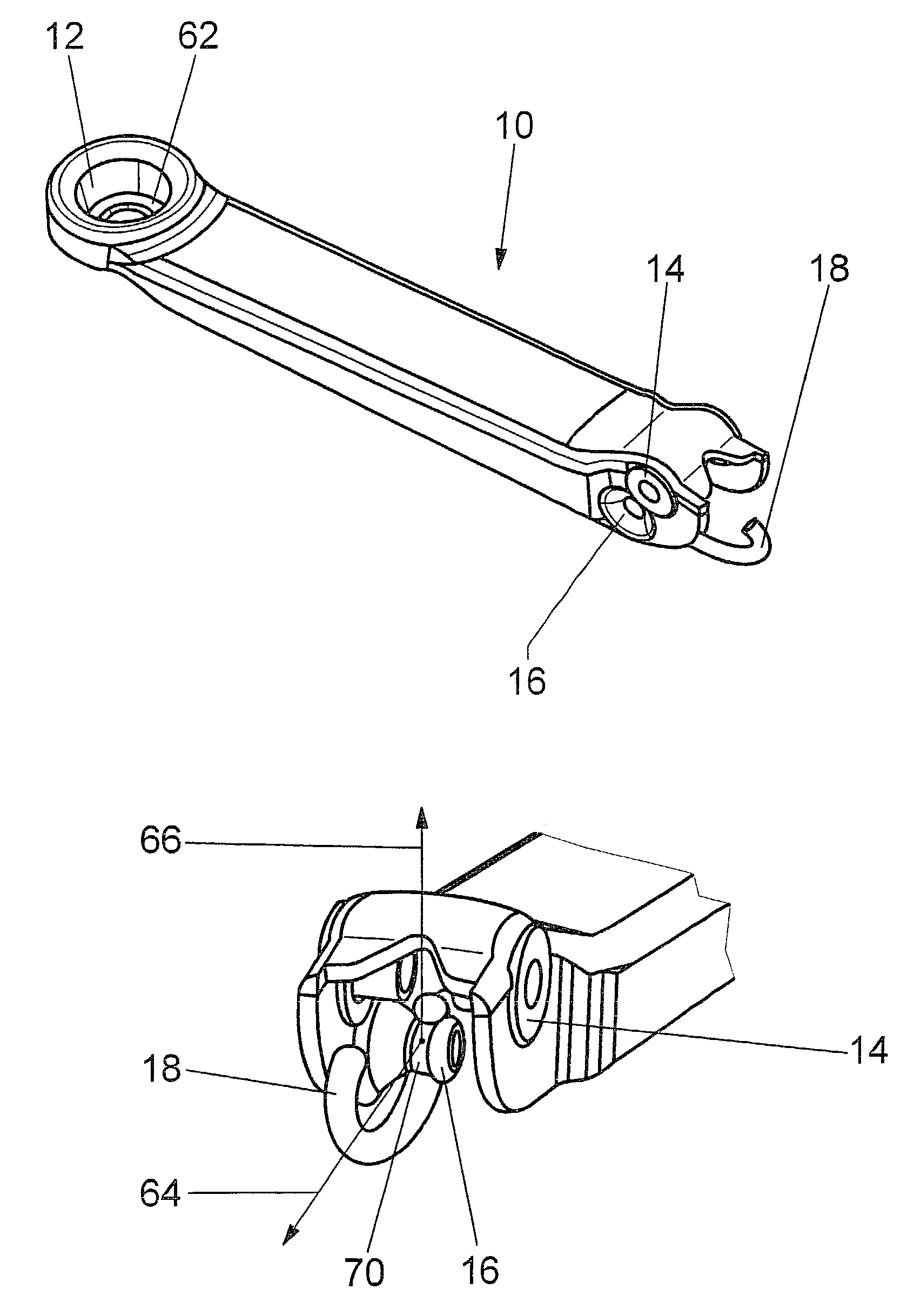
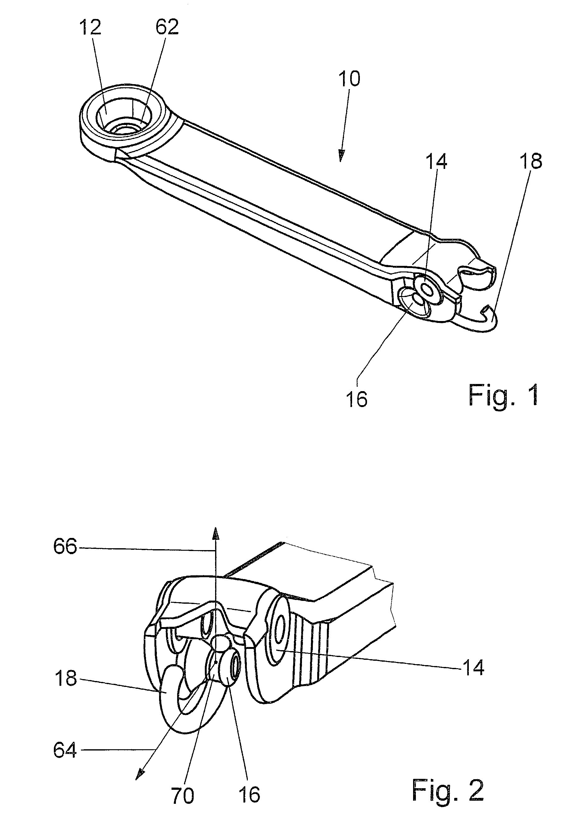
[0018]A mounting part 10 of a windshield wiper is provided at one end with a receiving opening 12 or 46 for a wiper shaft 44 (FIG. 10) and forms part 14 of a fold-away hinge at the other end (FIG. 1). Mounting part 10 also has a preformed spring mount 16 at this end, in which a c-shaped clip 18 of an extension spring (not shown) engages. Spring mount 16 is formed from a sidewall 24 of the u-shaped cross-section profile 20 by deep-drawing (FIGS. 2 and 9).

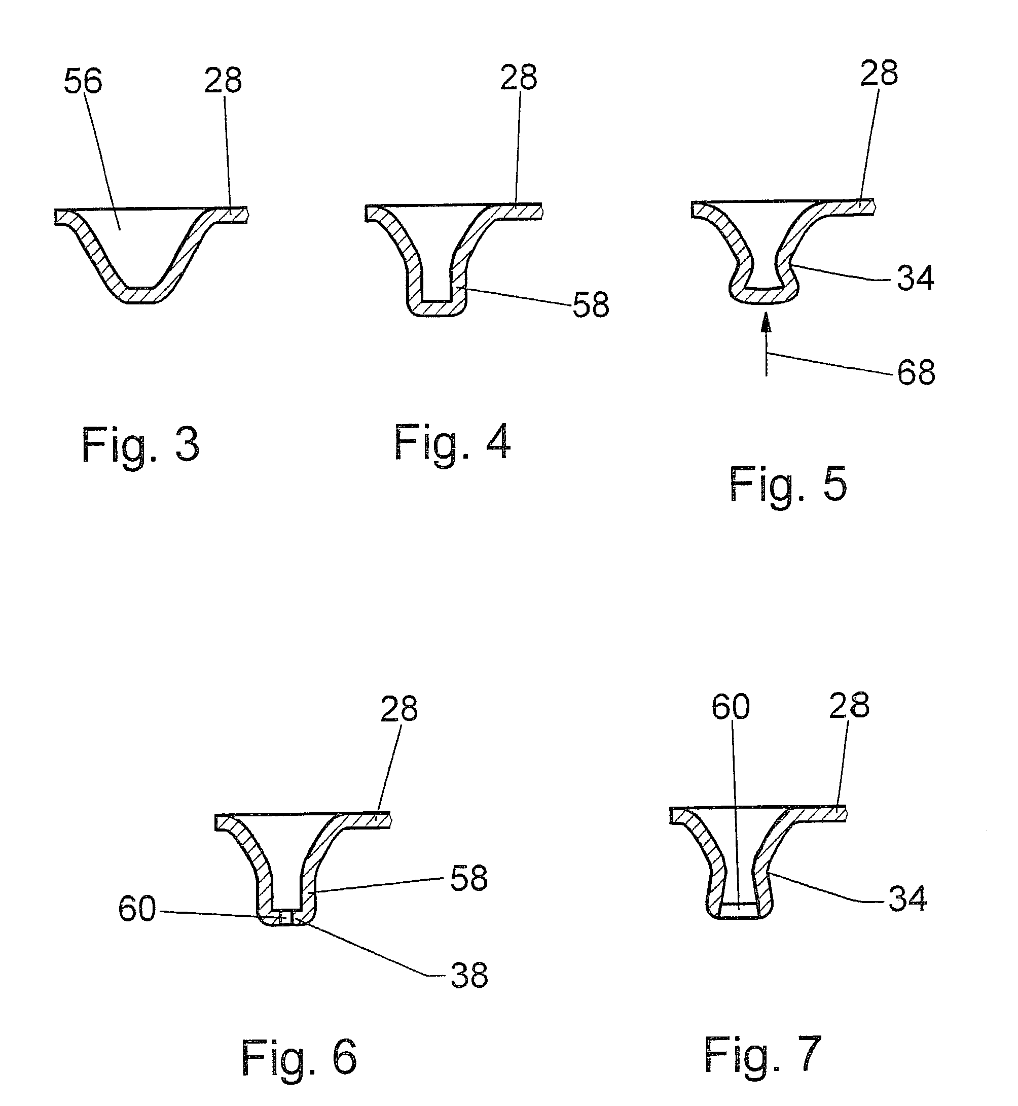
[0019]Relatively large tensile forces 64 and 66, respectively, are exerted on spring mount 16 from various directions, via c-shaped clip 18. The cross-section of spring mount 16 has a correspondingly sturdy design, by having a round hollow section which has the largest cross-section in the area transitioning to sidewall 24, and tapers to a necking 34. Necking 34 forms the engagement area of c-shaped clip 18 and, therefore, has a contour 36 which is adapted to the cross-section contour of c-shaped clip 18. The cross-section of spring ...


PUM

PropertyMeasurementUnit
bendingaaaaaaaaaa
timeaaaaaaaaaa
forcesaaaaaaaaaa

Abstract

A mounting part of a windshield wiper, having a receiving opening for a wiper shaft at one end, and forming a part of a fold-away hinge at the other end, and being formed from a flat sheet metal by deep-drawing, punching and bending and having a u-shaped cross-section profile and a spring mount. The spring mount is formed by deep-drawing from a sidewall of the u-shaped cross-section profile.

Description

BACKGROUND INFORMATION[0001]Known windshield wipers have a wiper arm, which is made up of a driven mounting part and a hinge member that is connected to it by a hinged joint and has a wiper rod. A wiper blade is pivoted at the free end of the wiper rod. The wiper blade is guided across the vehicle windshield during the swivel motion of the windshield wiper, an extension spring prestressing the fold-away hinge, so that the wiper blade is pulled toward the vehicle windshield.[0002]The extension spring is accommodated in the u-shaped cross-section profile of the articulated part and is suspended on the articulated part by one end using a cross-pin. By its other end, the extension spring is attached to a spring mount on the mounting part, via a c-shaped clip. In known mounting parts, this spring mount is either preformed or formed by a rivet pin. In one variant, for instance, mounting parts, designed as sheet metal form parts, use a pin as spring mount. During manufacture, this is press...

Claims


Application Information

Patent Timeline
Patent Type & Authority Patents(United States)
IPC IPC(8): B60S1/34
CPCB60S1/3438Y10T29/49622B60S1/3468B60S1/3459B60S1/34
Inventor ZIMMER, JOACHIM
Owner ROBERT BOSCH GMBH
Why Eureka
Try Eureka