Powertrain dynamic tilt test rig

Inactive Publication Date: 2006-05-02
GM GLOBAL TECH OPERATIONS LLC
View PDF6 Cites 16 Cited by
  • Summary
  • Abstract
  • Description
  • Claims
  • Application Information

AI Technical Summary

Benefits of technology

[0007]The use of electric drive motors and the gimballed frame layout enables the size of the test rig to be minimized to make it possible for its use in conventional engine test cells. Additionally, the use of electric power avoids the problems of poss

Problems solved by technology

Dynamic rigs capable of varying the attitude of an engine or transmission during testing to simulate dynamic acceleration inputs have been developed but are of very large physical size and not readily adaptable for use in the confines of conventional engine test cells.
Most such tilt rigs utilize

Method used


Image

  • Powertrain dynamic tilt test rig
  • Powertrain dynamic tilt test rig
  • Powertrain dynamic tilt test rig

Examples


Example

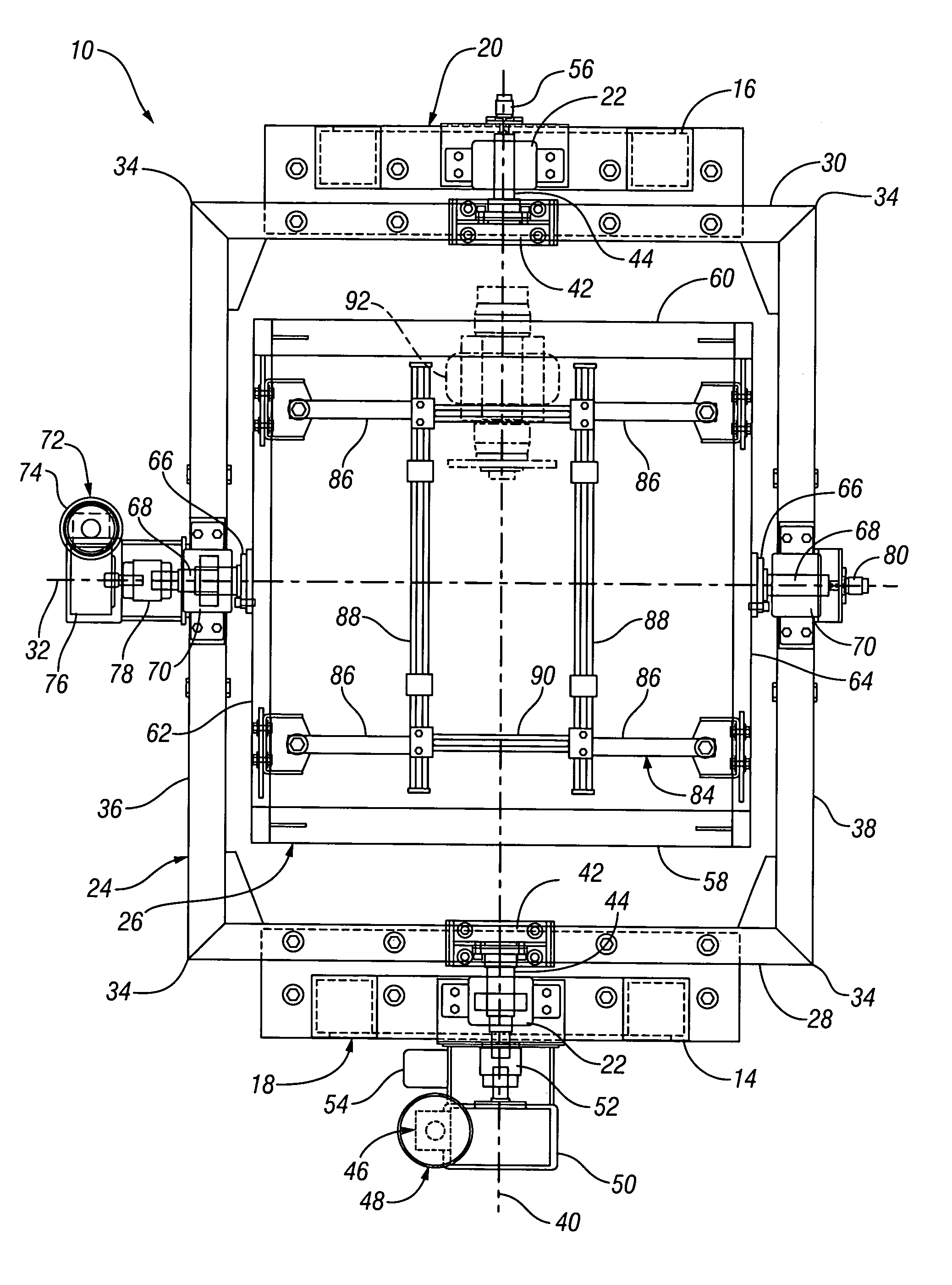
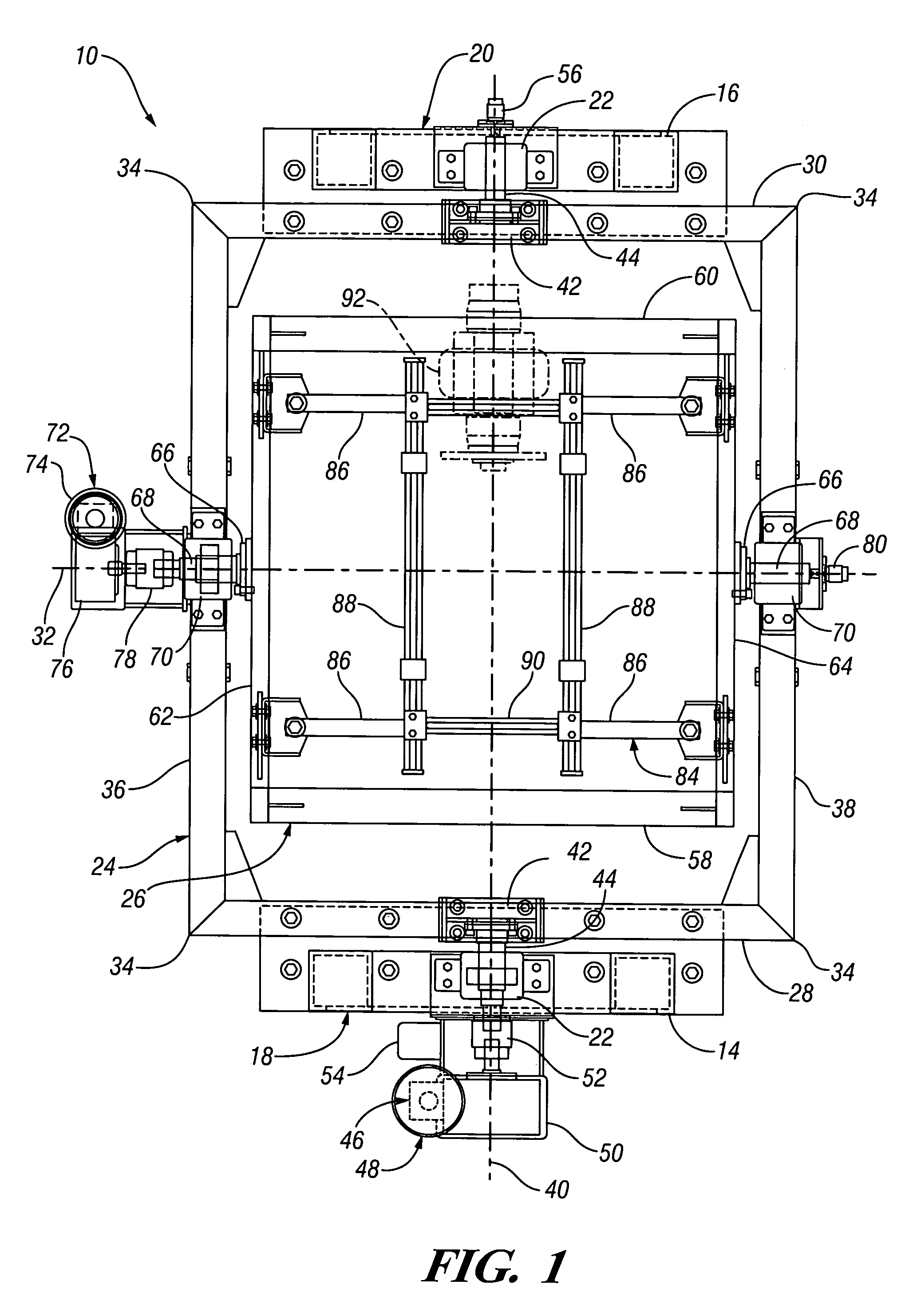
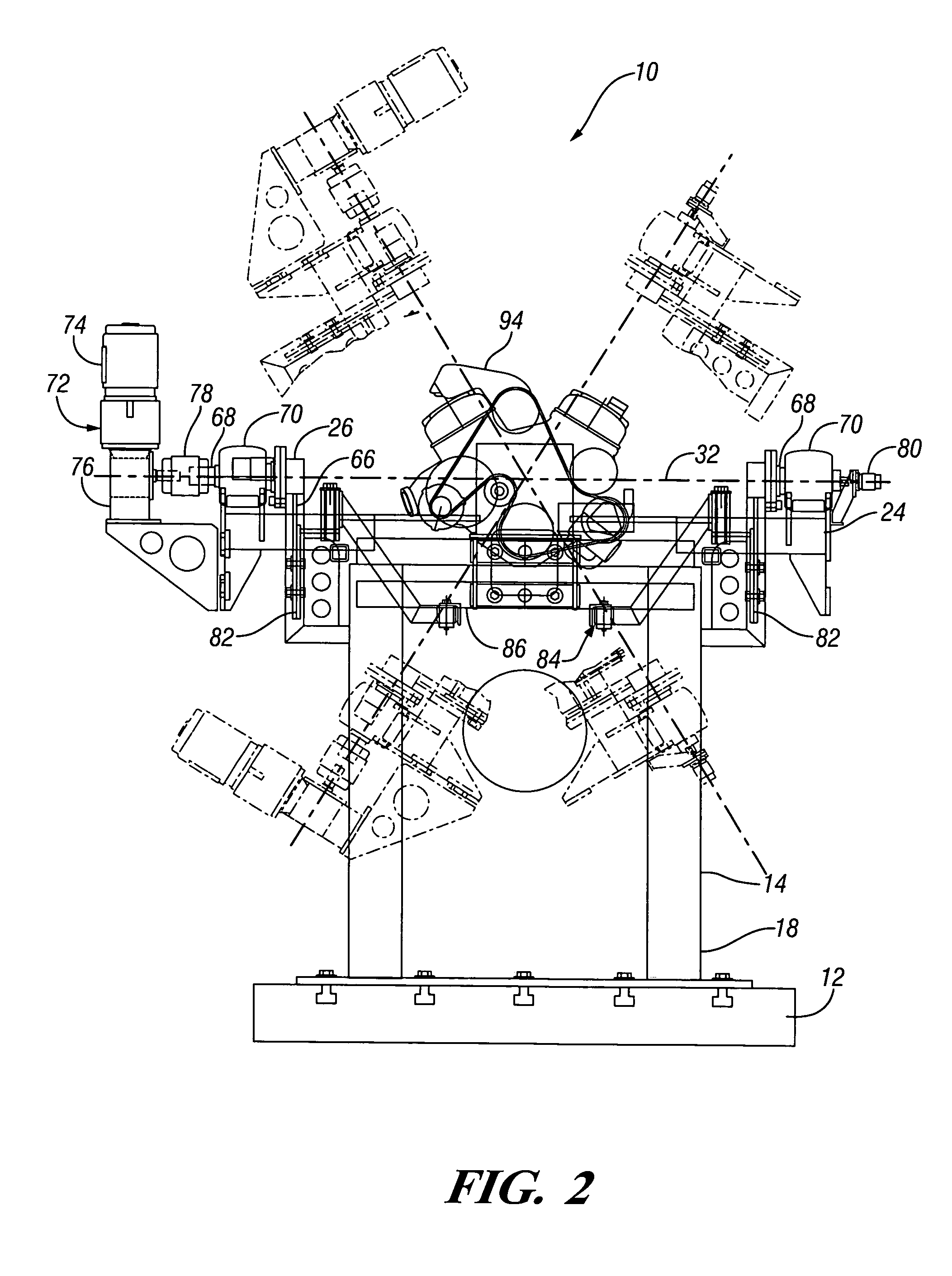
[0012]Referring now to the drawings in detail, numeral 10 generally indicates an exemplary embodiment of dynamic tilt test rig according to the invention. Test rig 10 is sized to fit within an engine test cell and is adapted for use in testing powertrain components, such as engines, transmissions, gear boxes and the like as well as for other possible uses.

[0013]Rig 10 may include a base but, in the disclosed embodiment, utilizes a separate base formed by a bed plate 12 mounted to the floor of an engine test cell. The rig 10 is supported by front and rear stanchions or stands 14, 16, respectively, which are independently secured to the bed plate 12. They extend laterally across front and rear ends 18, 20 of the test rig and respectively support gimbal bearings, one each on the front and rear stanchions 14, 16.

[0014]The test rig further includes an outer frame 24 and an inner frame 26. The outer frame includes front and rear end members 28, 30 spaced longitudinally from a transverse a...


PUM


Abstract

A test rig is provided for dynamic or static testing of a vehicle powertrain apparatus during operation in varying attitudes. A specific embodiment includes inner and outer frames carried one inside the other on gimbal bearings and pivotable on longitudinal and transverse axes. The inner frame carries a cradle for mounting a dynometer connected to an engine, transmission or other apparatus to be tested by tilting the apparatus to simulate the effects of vehicle acceleration in various directions. The rig may be supported on individual stanchions mounted to a test bed floor plate in an engine test cell and supporting the bearings for the outer frame. The pivotable frames are powered by electric motors through reduction gear boxes sized and mounted to minimize mass and inertia of the rig and allow mounting in an engine test cell. Programmable controls permit dynamic rocking of an engine operating under power.

Description

TECHNICAL FIELD[0001]This invention relates to test fixtures and, more particularly, to a dynamic tilt test rig adapted particularly for testing of vehicle powertrain components such as engines and transmissions during operation of the components in varying attitudes.BACKGROUND OF THE INVENTION[0002]It is known in the art to provide tilt rigs which have the capability of being used to simulate the effects of acceleration on fluids in powertrain components such as engines and transmissions, as well as other components. Simplified test rigs have commonly been used in engine test cells to simulate constant acceleration effects on engine oil in an operating engine.[0003]Dynamic rigs capable of varying the attitude of an engine or transmission during testing to simulate dynamic acceleration inputs have been developed but are of very large physical size and not readily adaptable for use in the confines of conventional engine test cells. Most such tilt rigs utilize hydraulic power, which i...

Claims


Application Information

Patent Timeline
IPC IPC(8): G01M19/00G01M99/00
CPCG01M13/027G01M13/025
Inventor GUSHMAN, RICHARD W.SWIECILO, JOHN
Owner GM GLOBAL TECH OPERATIONS LLC
Why Eureka
Try Eureka