Intake air control apparatus and method for internal combustion engine

a control apparatus and internal combustion engine technology, applied in engine controllers, machines/engines, valve arrangements, etc., can solve the problems of insufficient intake air and the worsening of torque responsive characteristics especially during acceleration, and achieve the effect of suppressing the influence of either relatively large mechanical delays or enhancing torque responsive characteristics

Active Publication Date: 2006-05-02
NISSAN MOTOR CO LTD
View PDF4 Cites 4 Cited by
  • Summary
  • Abstract
  • Description
  • Claims
  • Application Information

AI Technical Summary

Benefits of technology

[0007]It is, therefore, an object of the present invention to provide intake air control apparatus and method which are capable of enhancing a torque responsive characteristic, especially, during a transient state, namely, during an acceleration and are capable of effectively suppressing an influence of either relatively large mechanical delay variably operated valve mechanism of the first and second variably operated valve mechanisms.

Problems solved by technology

Especially, in a case where a relatively large difference in their mechanical delays is present (namely, one delay of the two variably operated valve mechanisms is relatively small but the other delay of the two variably operated valve mechanisms is relatively large), the intake air quantity is affected by the relatively large delay variably operated valve mechanism so that the intake air quantity is deviated from the target value.
In addition, there is a possibility that a torque responsive characteristic especially during an acceleration becomes worsened.

Method used


Image

  • Intake air control apparatus and method for internal combustion engine
  • Intake air control apparatus and method for internal combustion engine
  • Intake air control apparatus and method for internal combustion engine

Examples


first embodiment

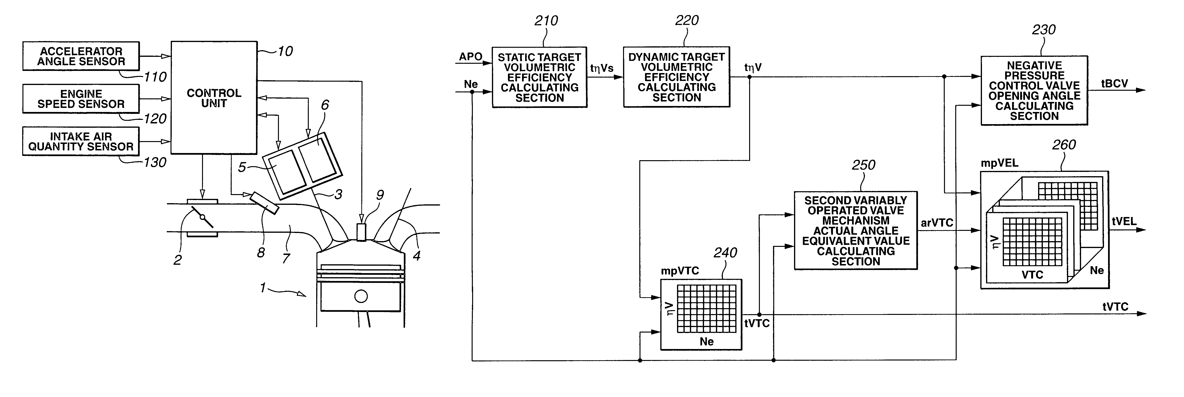
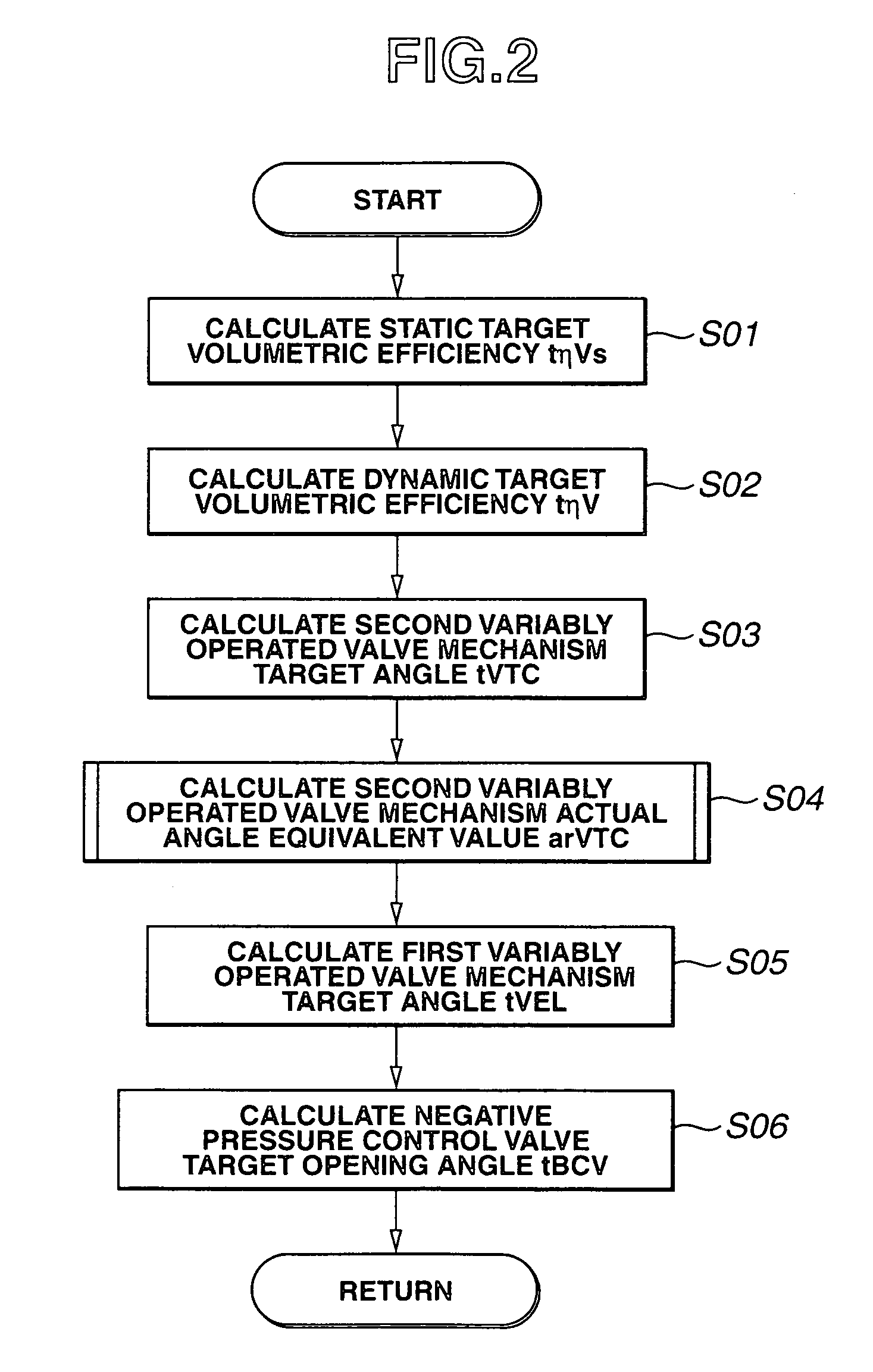
[0031]FIG. 2 shows a flowchart representing a calculation process of calculating a first variably operated valve mechanism target angle tVEL, a second variably operated valve mechanism target angle tVTC, and a negative pressure control valve target angle tBCV in the first embodiment shown in FIG. 1A. In FIG. 2, a volumetric efficiency ηV is used as a load parameter representing a load. However, another parameter representing the load may be used. First, control unit 10 calculates a static target volumetric efficiency tηVs from accelerator opening angle APO and engine speed Ne (step S01). Control unit 10 calculates a dynamic target volumetric efficiency tηV by adding an appropriate correction as will be described later to this static target volumetric efficiency tηVs at a step S02. Next, control unit 10 calculates second variably operated valve mechanism target angle tVTC from this dynamic target volumetric efficiency tηV and engine speed Ne at a step S03. At a step S04, control unit...

second embodiment

[0047]An action of the intake air control apparatus will be described on the basis of FIGS. 10A through 10D and FIG. 11.

[0048]FIGS. 10A through 10D show integrally a timing chart for explaining the operation of the second embodiment when the transient traveling (acceleration) is carried out. This is the action when the transient traveling is carried out such that the depression quantity of accelerator pedal (accelerator opening angle APO) is increased supposing that the engine speed is maintained constant at a certain revolution speed. FIG. 10A shows the variation of target volumetric efficiency tηV. FIG. 10B shows the variation of first variably operated valve mechanism angle (working angle) VEL. FIG. 10C shows the variation of second variably operated valve mechanism angle (central angle) VTC. FIG. 10D shows the variation of the engine torque. It is noted that a mechanical responsive characteristic of first variably operated valve mechanism 5 is very quick and is supposed to be ne...


PUM


Abstract

In intake air control apparatus and method for an internal combustion engine, a target angle calculating section calculates a target angle of one of first and second variably operated valve mechanisms from a target load in accordance with an accelerator opening angle and a present engine speed, a variably operated valve mechanism actual angle outputting section derives and outputs an actual angle of the one of the first and second variably operated valve mechanisms which is varied toward the target angle, and another target angle calculating section calculates another target angle of the other of the first and second variably operated valve mechanisms from a derived and outputted present corresponding variably operated valve mechanism actual angle equivalent value, the present engine speed, and the target load on the basis of a known relationship among four of the working angle, the central angle, the engine speed, and a load.

Description

BACKGROUND OF THE INVENTION[0001]1. Field of the Invention[0002]The present invention relates to intake air control apparatus and method for an internal combustion engine in which an intake air quantity sucked into a cylinder of the engine and, more particularly, relates to the intake air control apparatus and method for the internal combustion engine in which an intake air quantity control is achieved by means of a variable control of a valve lift characteristic of an intake valve (or intake valves).[0003]2. Description of the Related Art[0004]An intake air quantity is controlled by means of an opening angle control of a throttle valve, generally, installed within an intake air passage. As is well known in the art, in such a kind of control method, a pumping loss is large during middle and low loads of the engine in which the opening angle of the throttle valve is, particularly, small (narrow). Such a trial that a lift quantity or valve open and closure timings of the intake valve ...

Claims


Application Information

Patent Timeline
Patent Type & Authority Patents(United States)
IPC IPC(8): F01L1/34
CPCF01L1/34F01L13/0021F01L13/0015
Inventor MINAMI, YUTAROIWANO, HIROSHIOOBA, HIKARUONODA, NAONORI
Owner NISSAN MOTOR CO LTD
Why Eureka
Try Eureka