Fuel spout with a collection channel

a technology of fuel spout and collection channel, which is applied in the field of fuel spout, can solve the problems of gasoline vapors being suspected to contain other harmful toxic chemicals, irritate the nose, throat, lungs, etc., and achieve optimal drip management, pollution reduction, and reduction of harmful emissions

Inactive Publication Date: 2006-05-02
KNUBOX TECH
View PDF2 Cites 26 Cited by
  • Summary
  • Abstract
  • Description
  • Claims
  • Application Information

AI Technical Summary

Benefits of technology

[0011]The present invention is directed to fuel dispensing nozzles and more particularity to a spout of a fuel dispensing nozzle that reduces the amount of harmful emissions created during a fueling cycle. The spout of the nozzle has an inside surface that is in direct contact with a flow of fuel. After the flow of fuel is stopped, the residual amount of fuel adhered to the inside spout surface is encouraged to collect from an least one fuel collection channel. The collected fuel has fluid properties that are more optimal for drip management and pollution reduction. The at least one fuel channel results in less fuel dripping on the ground and less residual fuel, both of which harmfully evaporate into the air. A single channel may be used but depending upon particular applications and uses, more than one may be preferable. The one or more collection channels may be any common shape and may be used with vapor recovery and dripless style nozzles.

Problems solved by technology

Ground level ozone can potentially cause irritation to the nose, throat, lungs and bring on asthma attacks.
In addition, gasoline vapors are suspected to contain other harmful toxic chemicals, such as benzene.
Typically, when a nozzle is deactivated there is a delay before the user removes the nozzle spout from the container to be filled.
If the delay is insufficient, drops fall onto the ground or the local filling equipment.
Spilt fuel evaporates into the atmosphere and contaminates the ground.
Even waiting a significant amount of time before removing the nozzle will not ensure that dripping will not occur.
Although the aforementioned patents may potentially serve in the direction of their intended purposes, most are unlikely to reliably provide true dripless performance.

Method used


Image

  • Fuel spout with a collection channel
  • Fuel spout with a collection channel
  • Fuel spout with a collection channel

Examples


Embodiment Construction

[0023]Many of the fastening, connection, manufacturing and other means and components utilized in this invention are widely known and used in the field of the invention are described, and their exact nature or type is not necessary for a person of ordinary skill in the art or science to understand the invention; therefore they will not be discussed in detail.

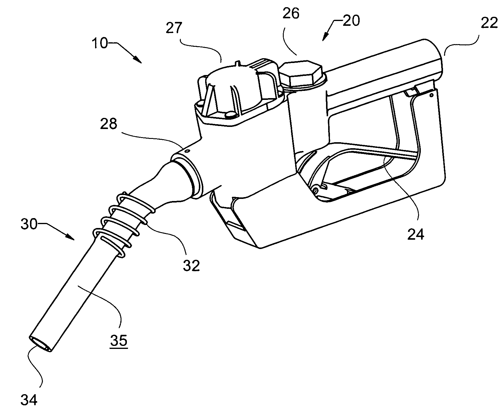
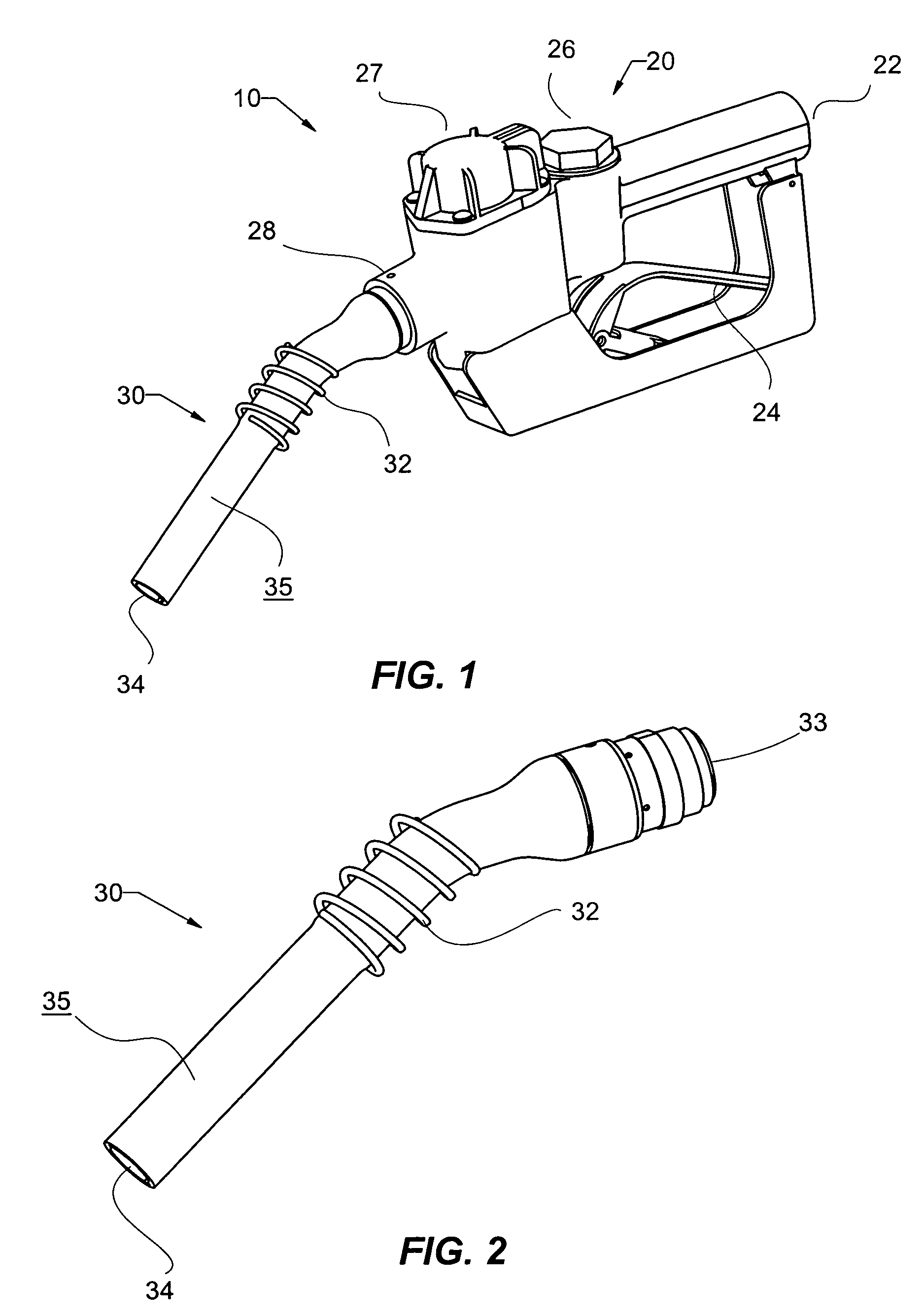
[0024]FIG. 1 shows a fuel dispensing nozzle assembly 10, comprised of a prior art nozzle assembly 20, and a spout assembly 30 according to the present invention. Prior art nozzle assembly 20 is used for dispensing fuel into a container to be filled (not shown) according to well known fuel dispensing apparatuses and practices. Fuel nozzle assembly 20 may be, but is not limited to, a standard nozzle as shown in FIGS. 1–8, or a vapor recovery nozzle as shown in FIG. 9. Generally, fuel is supplied to nozzle assembly 20 by connecting a hose assembly (not shown) to an inlet 22. The pressurized fuel supply travels to a valve assembly 2...


PUM

PropertyMeasurementUnit
lengthaaaaaaaaaa
volatileaaaaaaaaaa
volumeaaaaaaaaaa

Abstract

The present invention is directed to fuel dispensing nozzles and more particularity to a spout of a fuel dispensing nozzle that reduces the amount of harmful emissions created during a fueling cycle. The spout of the nozzle has an inside surface that is in direct contact with a flow of fuel. After the flow of fuel is stopped, the residual amount of fuel adhered to the inside spout surface is encouraged to collect and drip from at least one fuel collection channel. The at least one fuel channel results in less fuel dripping on the ground and less residual fuel, both of which harmfully evaporate into the air.

Description

CROSS REFERENCE TO RELATE APPLICATION[0001]This application claims priority from U.S. provisional patent application No. 60 / 547,693 filed on Feb. 23, 2004.STATEMENT REGARDING FEDERALLY SPONSORED R&D[0002]Not related to this application.TECHNICAL FIELD[0003]This invention relates to fuel nozzles and more particularly to a fuel dispensing spout that reduces the amount of pollution caused after the flow of fuel is stopped.BACKGROUND OF THE INVENTION[0004]Fuel dispensing nozzles are widely used and understood in the field. Early fuel nozzles are mainly comprised of a manual actuated valve and a metallic spout for directing fuel into a desired container. Many improvements have been made to fuel nozzles, including U.S. Pat. No. 4,453,578, which provide the means of automatically stopping fuel flow when the fuel reaches a desired level.[0005]In addition, many design improvements have been made regarding nozzle spouts. U.S. Pat. No. 5,765,609 describes a method for manufacturing an aluminum...

Claims


Application Information

Patent Timeline
Patent Type & Authority Patents(United States)
IPC IPC(8): B65B1/04
CPCB67D7/54B67D7/3209Y10T137/5762
Inventor KNIGHT, PAUL ATAKISAKI, WALT D
Owner KNUBOX TECH
Why Eureka
Try Eureka