
Fast response sprinkler head and fire extinguishing system

a sprinkler head and fast technology, applied in the field of sprinklers, can solve the problems of ineffective firefighting in these large warehouses, water is actually delivered, and the quantity of water expelled from the sprinkler is not acceptable in this high temperature zone, so as to improve the convective heat flow, reduce costs, and simplify the installation of the sprinkler system

Inactive Publication Date: 2006-05-02
AMERICAN TELEPHONE & TELEGRAPH CO
View PDF47 Cites 57 Cited by
  • Summary
  • Abstract
  • Description
  • Claims
  • Application Information

AI Technical Summary

Benefits of technology

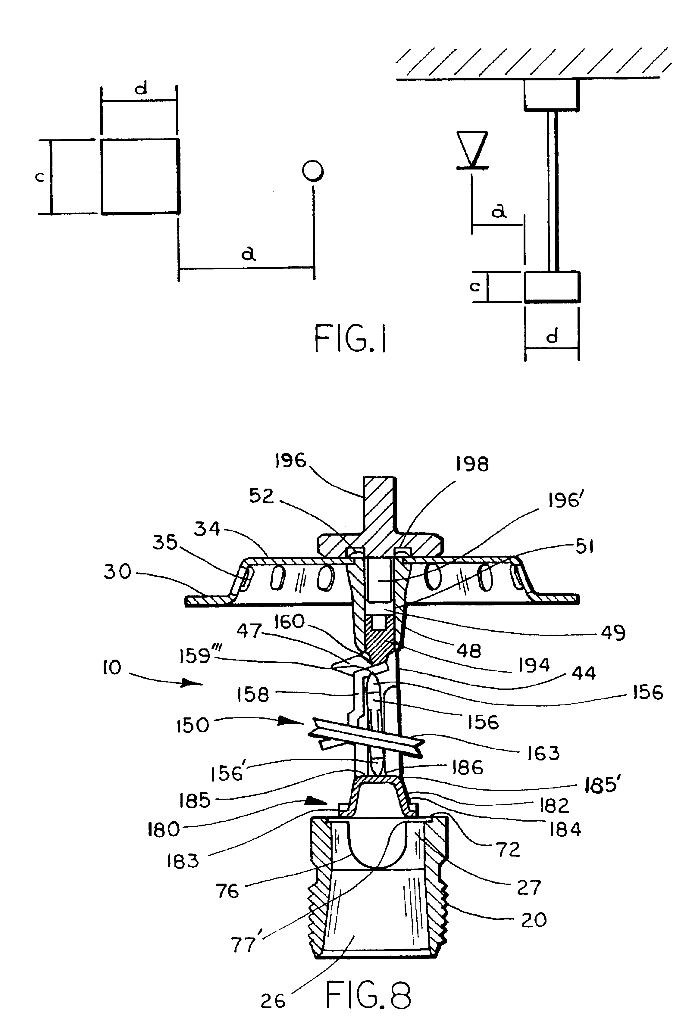
[0033]According to another aspect of the present invention, a fire sprinkler system is provided for suppressing a fire in an enclosure, wherein the enclosure contains at least one generally horizontal obstruction of a preselected dimension positioned below the ceiling, and above the floor. The enclosure contains a particular commodity classification, and the fire sprinkler system includes a fire extinguishing fluid supply line having a diameter less than or equal approximately 3.0 inches. At least one upright sprinkler head is attached to the fluid supply line and in fluid communication therewith. The upright sprinkler head is positioned along the fire extinguishing fluid supply line such that the lateral or horizontal distance between the upright sprinkler head and the obstruction is less than approximately three times the width or outer diameter of the obstruction, depending upon the shape of the obstruction. The use of an upright sprinkler head which is placed a horizontal distance less than approximately three times the width or outer diameter of the obstruction reduces the complexity involved in the installation of a sprinkler system and provides increased protection for enclosures having obstructions.
[0034]According to yet another aspect of the invention, a method for suppressing a fire in an enclosure having at least one generally horizontal obstruction supported a preselected distance below the ceiling includes the steps of providing a fire extinguishing fluid supply line within the enclosure having a diameter less than or equal to approximately 3.0 inches and attaching at least one upright sprinkler to the fire extinguishing fluid supply line. The upright sprinkler has a K value greater than or equal to approximately 13.5, and a fusible trigger assembly having a fusing temperature between approximately 155° F. and 175° F. Utilizing an upright sprinkler having a K value greater than 13.5 and a trigger assembly having a fusing temperature in the range of 155° F. to 175° F., in combination with a 3.0 inch or less diameter fluid supply line, provides an effective method for extinguishing or suppressing a fire.
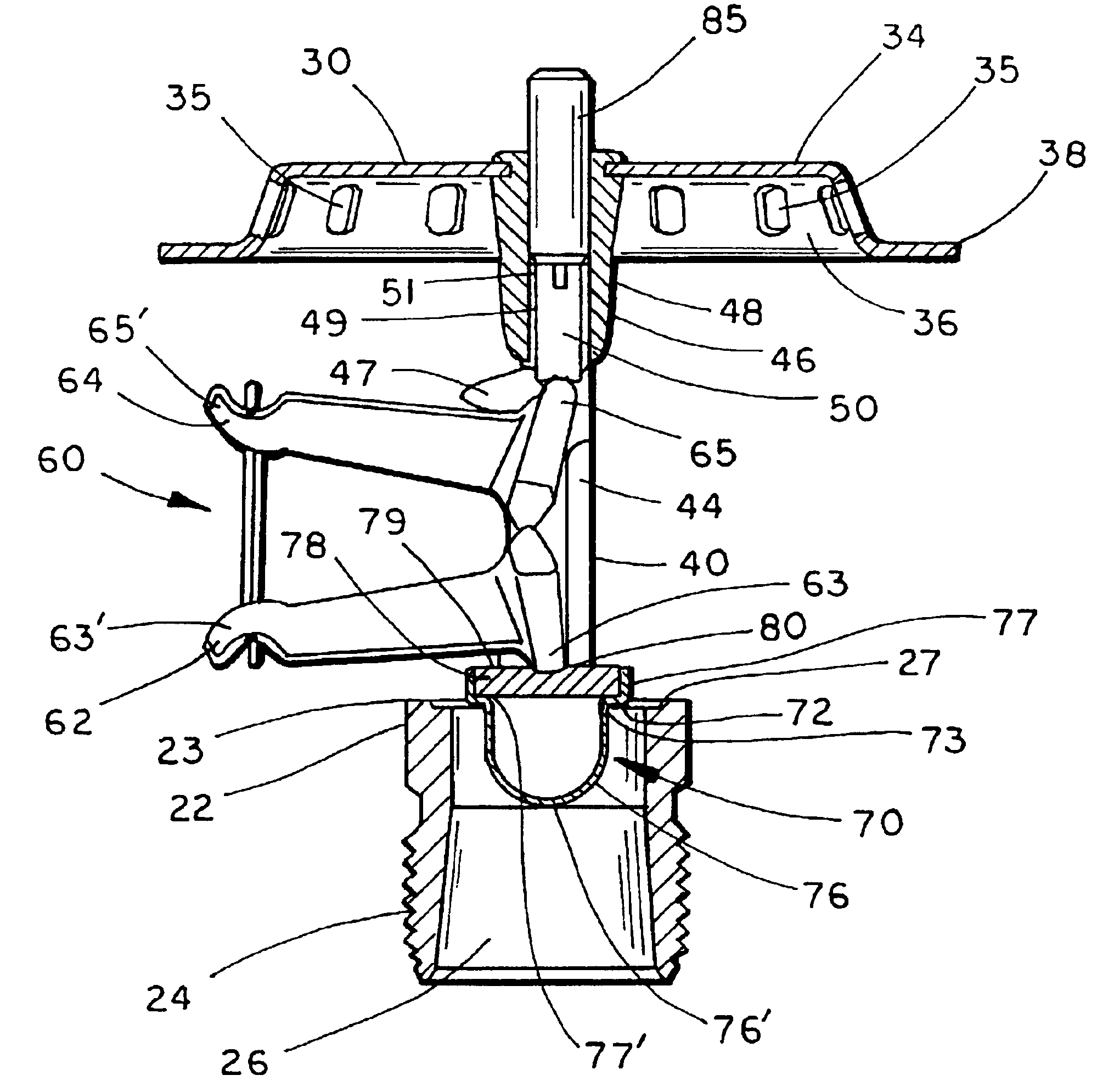
[0035]According to still yet another aspect of the present invention, an upright sprinkler head is disclosed having a sprinkler body configured for attachment to a fire extinguishing fluid supply line and having a K value of at least approximately 13.5. A deflector is coupled to the sprinkler body and has an impact surface configured to generate an optimum spray distribution pattern of fire extinguishing fluid over an area to be protected. The deflector includes a generally planar member having a perimeter and a skirt depending outwardly therefrom at a preselected angle from the vertical, which is between approximately 12° and 26°. An annular ledge extends horizontally from the skirt. The combination of a K value of at least 13.5 and a deflector having a planar member, a skirt depending outwardly therefrom at a preselected angle, and an annular ledge provides an effective upright sprinkler head for use in suppressing or extinguishing a fire.
[0036]According to still yet another aspect of the invention, a fire sprinkler system for use in suppressing a fire in an enclosure having at least one generally horizontal obstruction with a preselected dimension positioned below the ceiling and above the floor, and containing a particular commodity classification includes a fire extinguishing fluid supply line having a diameter less than or equal to approximately 3.0 inches, and at least one upright sprinkler having a deflector and extending from the fire extinguishing fluid supply line. The at least one upright sprinkler includes a K value of at least approximately 13.5, and includes a fusible trigger assembly having fusing temperature between approximately 155° F. and 175° F. The deflector of the at least one upright sprinkler is positioned a preselected vertical distance above the bottom of the obstruction. Utilizing the upright sprinkler head of the present invention permits its placement a horizontal distance above the obstructions, which in turn greatly simplifies the installation of the sprinkler system and thus reduces costs.
[0037]According to a further aspect of the invention, a fusible link for a sprinkler head having a first lever and a second lever comprises a first plate formed with a first channel and at least one air aperture, and a second plate formed with a second channel and at least one air aperture. A layer of head fusible material joins the first and second plate. The first and second channel extend in opposite directions and the at least one air aperture of the first plate is in registration with the at least one air aperture of the second plate when the fusible link is in the assembled condition. The use of registering air apertures in the fusible link provides air passages to increase the convective heat flow through the fusible link, and hence increases response time, enabling the fusible link to be used in applications wherein fast response is necessary to suppress or extinguish a fire.
[0038]The present invention provides a fast response upright sprinkler head capable of discharging a sufficient output of water or other fire extinguishing fluid, and effectively alters the trajectory of the water so as to develop a spray distribution pattern about a preselected area. The spray distribution pattern generated by the sprinkler head of the present invention provides an ADD in excess of the RDD for a given fuel package, and thus permits the sprinkler head to be used in commercial or industrial warehouse applications requiring fire suppression. Additionally, by using the fast response upright sprinklers of the present invention, a fire extinguishing system can be implemented wherein the fast response upright sprinkler head is placed in proximity to, and horizontally above, an obstruction. The ability to place the fast response, upright sprinkler head in proximity to these obstructions enables the fast response upright sprinkler head to provide an optimum spray distribution pattern about the obstruction and thereby provides greater fire protection in the event a fuel package is ignited directly below or approximately directly below the obstruction.

Problems solved by technology

Traditional sprinklers, designed and installed so as to provide “fire control,” have proven ineffective in combating fires ignited in these large warehouses.
As the vertically stacked pallets may exceed over twenty feet in height, fires ignited within these pallets produce a plume of combustion gasses which rapidly travels upward and subsequently impacts the ceiling of the warehouse.
The rapid generation of these combustion gases creates a zone of high temperature above the fire, and thus when the sprinkler head is activated, an unacceptable quantity of water expelled from the sprinkler is evaporated within this high temperature zone before it reaches the site of the fire.
As a result, less water is actually delivered to the fire and hence prevents effective fire control.
The rapid movement of the combustion gases along the ceiling results in the actuation of a large number of sprinkler heads located a remote distance from the perimeter of the fire.
The mass actuation of sprinkler heads within the warehouse produces several unacceptable consequences.
First, the near simultaneous actuation of a large number of sprinkler heads produces a significant decrease in the water pressure delivered to each individual sprinkler head.
Furthermore, actuation of remotely located sprinkler heads results in water damage to the product protected by such sprinklers.
The decrease in the ADD as a function of time is also due to the growth of the fire plume, which results in an increasing water evaporation rate, and thus reduces the quantity of water actually delivered to the fuel package.
Despite these attempts, heretofore, the industry has been unable to generate an upright sprinkler head capable of achieving ESFR standards, and has only produced pendent sprinklers having the requisite ADD criteria.
The inability of the industry to generate an ESFR sprinkler having an upright design has presented problems in the industry, specifically, in the retrofitting of warehouses.
This, in turn, has increased the cost and complexity of installing an ESFR sprinkler system.
Failure to conform or operate successfully within the NFPA guidelines effectively prohibits the commercial viability of a particular sprinkler design or its installation.
Furthermore, the various sections of NFPA 13 (1999 ed.) has increased the complexity of the installation procedure of ESFR sprinklers in areas wherein obstructions are present.
In addition, as a conventionally sized warehouse or storage facility may contain many different types of obstructions, the installation of sprinkler systems in these facilities is often a complex procedure.
§4-11.5.2, and the various sections of NFPA 13 (1999 ed.) has resulted in particular areas receiving only a marginal quantity of water and thus, are particularly vulnerable to the generation and growth of a fire.

Method used


Image

  • Fast response sprinkler head and fire extinguishing system
  • Fast response sprinkler head and fire extinguishing system
  • Fast response sprinkler head and fire extinguishing system

Examples


example

[0089]In a fire sprinkler system test conducted by the Factory Mutual Research Corporation utilizing an array of upright sprinkler heads according to the present invention, and obstructed by a particular bar joist configuration, the upright sprinkler head of the present invention exhibited fire suppression performance for the FMRC standard plastic commodity.

[0090]The test was conducted under a 30 foot high ceiling, having depending therefrom a bar joist having a bottom cord approximately four inches in width. Both the ignition location (i.e., the area in which the fire was ignited) and the bar joist were positioned directly under a single upright sprinkler head of the sprinkler head array. The fluid supply line responsible for transporting fluid to the upright sprinkler head located above the ignition location was positioned perpendicular to the bar joist, while its bottom cord was positioned immediately beneath the supply pipe. The commodity tested was FMRC standard plastic commodi...


PUM


Abstract

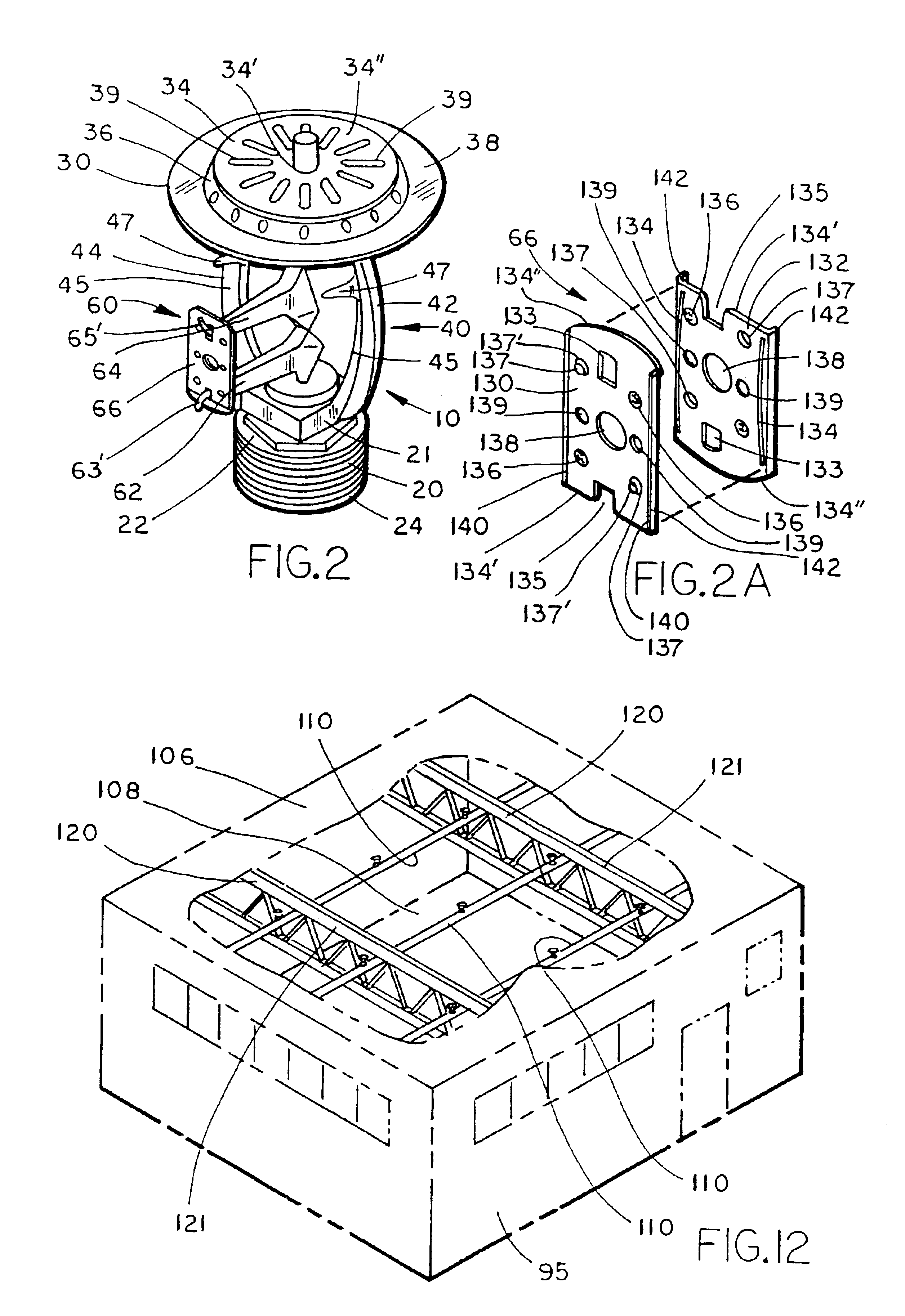
A fast response, upright sprinkler head includes a body having a central orifice through which fire extinguishing fluid is expelled through an outlet end. A yoke, attached to the exterior surface of the sprinkler body, extends beyond the outlet end of the sprinkler body and is connected at its apex to a deflector. A fusible trigger assembly is coupled to the yoke and the outlet end of the sprinkler head. The deflector is formed with a planar member having a skirt depending therefrom and an annular ledge extending horizontally from the skirt. The skirt depends from the planar member in an outward direction at a pre-selected angle from the vertical, and is formed with a plurality of through-holes. The fast response upright sprinkler head is configured to have a K value of at least 13.5, while the fusible trigger assembly has a fusing temperature between approximately 155° F. and 175° F. to thereby provide a fast response sprinkler head capable of expelling a sufficient density of water during the early stages of fire development. The angle of the skirt, as well as the through holes formed therein, alter the trajectory of the water to thereby provide a hemispheric pattern of large water droplets capable of penetrating the fire plume and reaching the fire source in order to suppress or extinguish the same. In another aspect of the invention, the fast response upright sprinkler head is used in a fire extinguishing system and method wherein the upright sprinkler head is placed in proximity to a horizontal obstruction depending from, or otherwise supported, a preselected distance from the ceiling of an enclosure. The upright sprinkler system of the present invention develops an effective spray distribution pattern about the obstruction to thereby suppress a fire positioned directly below, or approximately below, the obstruction.

Description

CROSS-REFERENCE TO RELATED APPLICATION[0001]This application is a divisional application of U.S. application Ser. No. 09 / 579,552, filed May 26, 2000 now U.S. Pat. No. 6,585,054, which claims priority from U.S. Provisional Pat. Application Ser. No. 60 / 136,498, filed May 28, 1999, the disclosure of which is hereby incorporated herein by reference.BACKGROUND OF THE INVENTION[0002]The present invention relates to sprinklers used in automatic fire extinguisher systems for buildings and the like, and in particular, relates to a fast response sprinkler head and fire sprinkler system for use in environments wherein one or more obstructions are positioned in proximity to the sprinkler head.[0003]Automatic sprinklers have long been used in automatic fire extinguishing systems for buildings in order to disburse a fluid to control a fire. Typically, the fluid utilized in such systems is water, although systems have also been developed to disburse foam and other materials. Historically, sprinkle...

Claims


Application Information

Patent Timeline
Patent Type & Authority Patents(United States)
IPC IPC(8): A62C37/08A62C31/02A62C37/12A62C37/36B05B1/26
CPCA62C31/02B05B1/265A62C37/12
Inventor THOMAS, PETER W.DEEGAN, THOMAS G.FRANSON, SCOTT T.BOSMA, MICHAEL J.DORNBOS, DELWIN G.
Owner AMERICAN TELEPHONE & TELEGRAPH CO
Learn More