Method and apparatus for making and locking members for dispensing packaging products

a technology for locking members and packaging products, applied in the field of method and apparatus for making and locking members for dispensing packaging products, electronic product packaging, etc., can solve the problems of personal injury, substantial internal stress in the package, and personal injury from newly cut packaging edges, etc., to facilitate quick engagement and quick disengagement

Inactive Publication Date: 2006-05-02
MONSTER
View PDF10 Cites 16 Cited by
  • Summary
  • Abstract
  • Description
  • Claims
  • Application Information

AI Technical Summary

Benefits of technology

[0006]The inner packaging member may have a structure for retaining at least one product, such as at least one compartment. The retaining structure may also have a structure for separating the at least one compartment, such as a wall structure. The at least one compartment may have at least one complementary contour for accommodating the at least one product. The at least one product may be at least one power or battery cell. The inner packaging member and the outer packaging member may each have at least one coincident orifice for facilitating displaying the at least one product by hanging. The inner packaging member may be formed from a material having an optical property such as transparency, translucency, and opacity. The inner packaging member may have a floor member for facilitating standing of the apparatus on a horizontal surface.
[0008]The packaging apparatus may further have a structure for mating and locking the outer packaging member to the inner packaging member. The mating and locking structure may be provided by at least one recess formed in the inner packaging member and at least one complementary formed on the outer packaging member to be inserted into the at least one recess. The mating and locking structure may operate using at least one mechanism, such as a compression-fit and an interference-fit. The mating and locking structure facilitates quick-engagement and quick-disengagement of the inner packaging member and the outer packaging member. The outer packaging member and the inner packaging member may also together have a complementary geometric configuration. The outer packaging member and the inner packaging member together may form a hopper / feeder arrangement for dispensing the at least one product by gravity-feed.
[0009]Advantages of the present invention include, but are not limited to, rapid engagement and disengagement of the packaging portions, thereby eliminating the related art need for scissors to cut through the typically thick polymer packaging in order to access the product; reducing the chance of injury to the consumer by eliminating the sharp edges arising from cutting related art packages; and providing easy dispensing of the product by gravity-feed. Other features of the present invention are disclosed, or are apparent in the section entitled “Detailed Description of the Invention.”

Problems solved by technology

With respect to the current art hard plastic packaging, the consumer must cut through the plastic using heavy shears in order to access the electronic product, risking personal injury from the newly cut packaging edges.
Because the current art plastic packaging is typically heavy gauge, substantial internal stresses will develop in the package during the consumer's attempt to remove the product.
During such attempted removal, the cut packaging may, and often does, spring-back on the consumer, thereby causing personal injury.
In addition, the current art hard plastic packaging, once cut, cannot readily store nor dispense the product.

Method used


Image

  • Method and apparatus for making and locking members for dispensing packaging products
  • Method and apparatus for making and locking members for dispensing packaging products
  • Method and apparatus for making and locking members for dispensing packaging products

Examples


Embodiment Construction

.”

BRIEF DESCRIPTION OF THE DRAWING

[0010]For a better understanding of the present invention, reference is made to the below-referenced accompanying Drawing. Reference numbers refer to the same or equivalent parts of the present invention throughout the several figures of the Drawing.

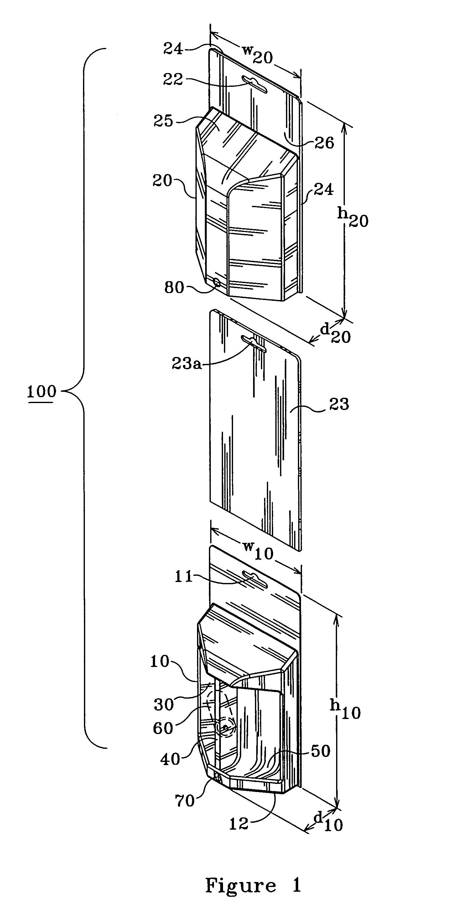
[0011]FIG. 1 is a perspective view of the apparatus for packaging, displaying, dispensing, and storing at least one product in a dissembled state, in accordance with the present invention.

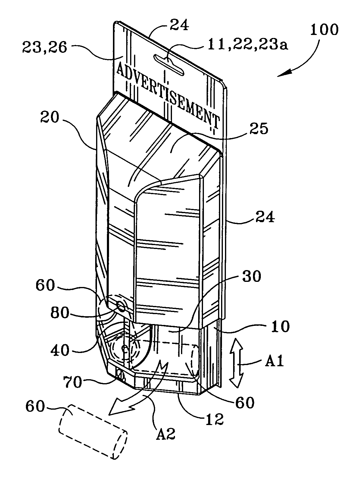
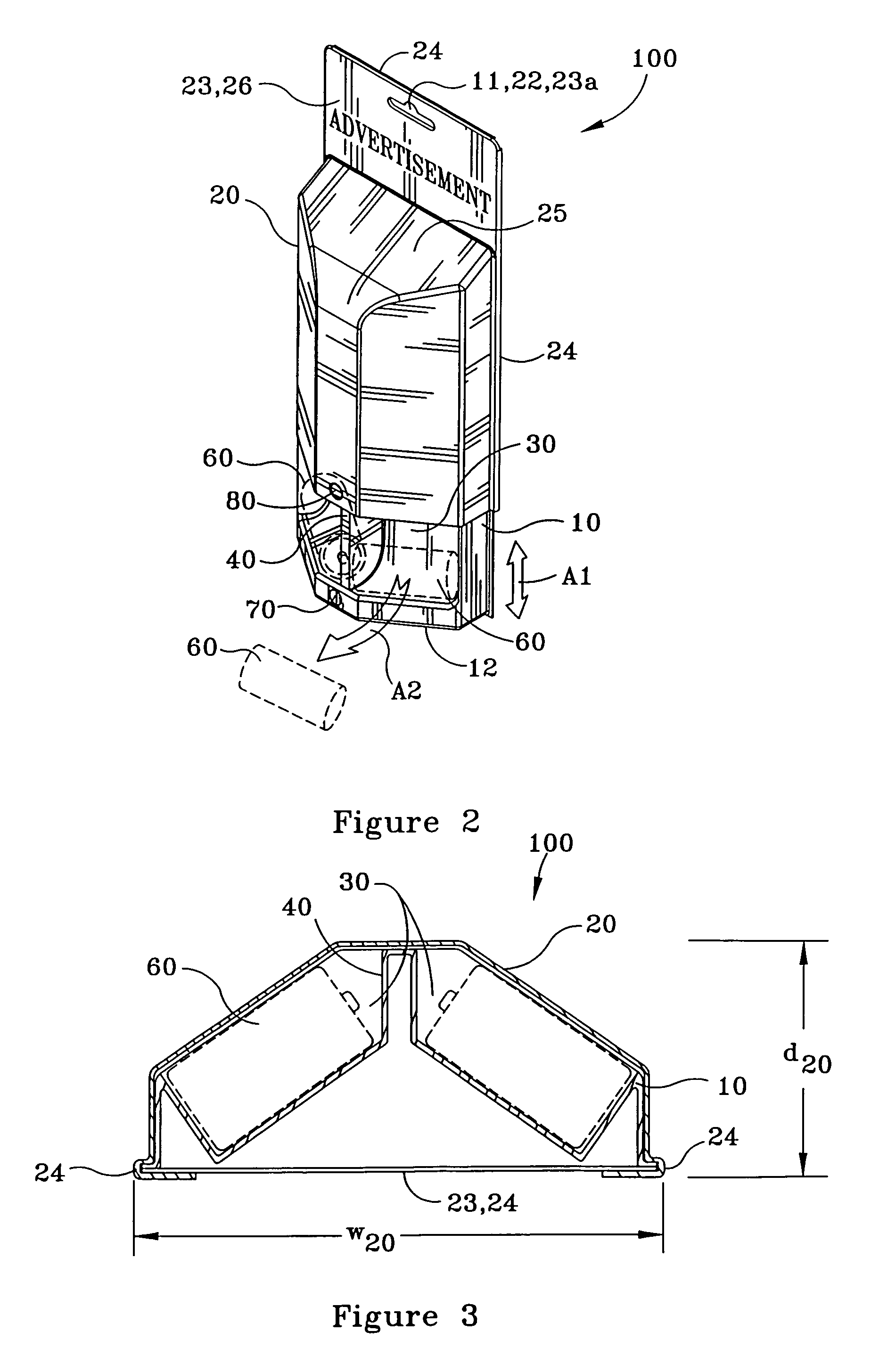
[0012]FIG. 2 is a perspective view of the apparatus of FIG. 1, in a partially assembled state, illustrating the feeder / hopper operation, in accordance with the present invention.

[0013]FIG. 3 is a width-wise cross-sectional view of the apparatus of FIG. 1, illustrating the disposition of the product being packaged, in accordance with the present invention.

[0014]FIG. 4 is a height-wise cross-sectional view of the apparatus of FIG. 1, illustrating the dissembled mating and locking structure, in accordance with the present ...


PUM

PropertyMeasurementUnit
gravity-feedaaaaaaaaaa
optical propertyaaaaaaaaaa
transparencyaaaaaaaaaa

Abstract

A method and an apparatus for packaging, displaying, dispensing, and storing at least one product, having an inner packaging member and an outer packaging member, the outer packaging member being slidably mounted over the inner packaging member. The inner packaging member may have a structure for retaining a product, such a compartment, a structure for separating the compartment, such as a wall, a complementary contour for accommodating the product, such as a power or a battery cell. The outer packaging member may have a backing member, such as at least one insert, a flange for accommodating and supporting the at least one insert, a roof member, and a section for accommodating an advertisement of the at least one product. The packaging apparatus may have a structure for mating and locking the outer packaging member to the inner packaging member for facilitating engagement and disengagement. The outer packaging member and the inner packaging member may together have a complementary geometric configuration.

Description

CROSS-REFERENCE TO RELATED APPLICATION(S)[0001]The present application is technologically related to a concurrently filed U.S. design patent application Ser. No. 10 / 838,776.COPYRIGHT NOTICE AND LIMITED AUTHORIZATION FOR USE[0002]A portion of the disclosure of the present patent application contains material which is subject to copyright protection. The copyright owner has no objection to the facsimile reproduction by anyone of the patent document or the patent disclosure, as it appears in the United States Patent and Trademark Office patent file or records, but otherwise reserves all rights under the copyright laws of the United States (17 U.S.C. §106).FIELD OF THE INVENTION[0003]The present invention involves product packaging. More particularly, the present invention involves electronic product packaging. Even more specifically, the present invention involves power cell packaging for display, dispensing, and storing.BACKGROUND OF THE INVENTION[0004]Currently, electronic products a...

Claims


Application Information

Patent Timeline
Patent Type & Authority Patents(United States)
IPC IPC(8): B65D73/00B65D43/12B65D85/00B65H1/00B65D75/36B65D85/88
CPCB65D75/366B65D2585/88B65D2575/363
Inventor LEE, KENDREWYAMAMOTO, YASUHIRO
Owner MONSTER
Why Eureka
Try Eureka