Device for dispensing plastic fasteners

a technology for fasteners and devices, applied in the field of plastic fasteners, can solve the problems of compromising the ability of conventional plastic fastener dispensing devices to generate fasteners with optimal h-, failure to properly and failure to sever the rails of the supply at the approximate midpoint, etc., and achieves the effect of convenient use and inexpensive manufacturing

Active Publication Date: 2006-05-02
AVERY DENNISON CORP
View PDF6 Cites 1216 Cited by
  • Summary
  • Abstract
  • Description
  • Claims
  • Application Information

AI Technical Summary

Benefits of technology

[0020]It is yet still another object of the present invention to provide a system as described above which has a limited number of parts, which is easy to use and which is inexpensive to manufacture.

Problems solved by technology

However, it has been found that conventional plastic fastener dispensing devices often fail to sever the rails of the supply of ladder stock at the approximate midpoint between successive filaments.
This failure to properly sever the rails of the supply of ladder stock at the approximate midpoint between successive filaments can be caused by, inter alia, manufacturing tolerances in the thickness of the rails and filaments of the ladder stock which, in turn, can create lag, or rubbing, of the ladder stock within feed tracks in the fastener dispensing device.
The lag created between the ladder stock and the fastener dispensing device precludes the feed mechanism for the device from adequately advancing the lowermost fastener in the ladder stock to the appropriate stop position within the device prior to the cutting process.
Because the ladder stock is inadequately advanced by the feed mechanism, the severing process cuts the rails of the ladder stock at a location other than at the midpoint between successive fasteners.
As a result, the device will dispense plastic fasteners which fail to have each end of its filament accurately bisect a corresponding cross-bar, thereby compromising its ability to generate fasteners which have the optimal H-type configuration.
Although well known and widely used in commerce, fastener dispensing devices which include internal and external fine tune adjustment means to its feed mechanism have been found to suffer from a notable drawback.
However, inexperienced users often introduce misalignment into the feed mechanism by manipulating its external adjustment means.
As can be appreciated, the external adjustment means for calibrating the feed mechanism is extremely sensitive and requires a certain level of precision which is typically found with only the more experienced and methodical users.
As a result, it has been found that, more often than not, the presence of an external adjustment means causes the user to introduce misalignment into the feed mechanism which is not present upon completion of its manufacture, which is highly undesirable.

Method used


Image

  • Device for dispensing plastic fasteners
  • Device for dispensing plastic fasteners
  • Device for dispensing plastic fasteners

Examples


Embodiment Construction

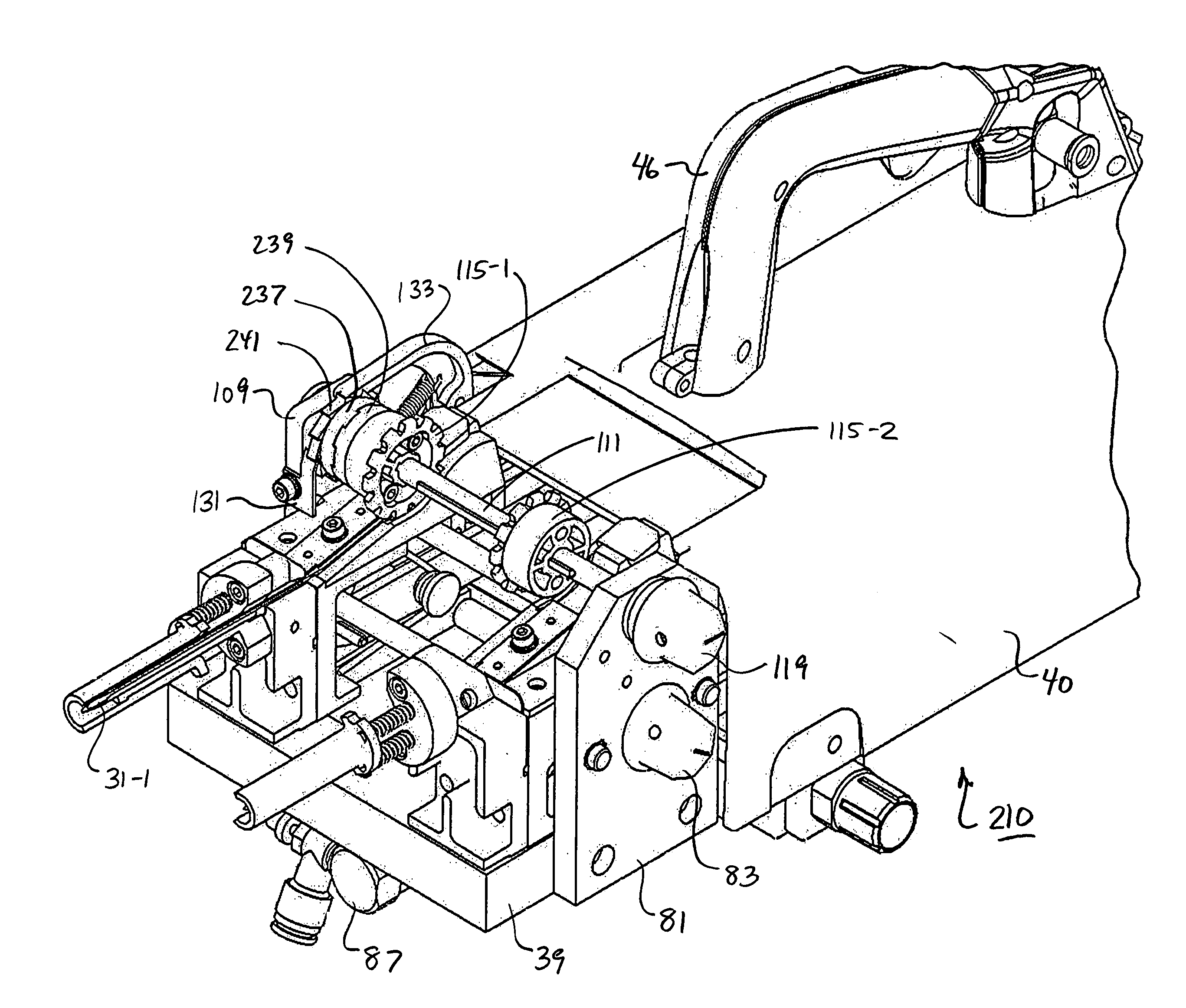
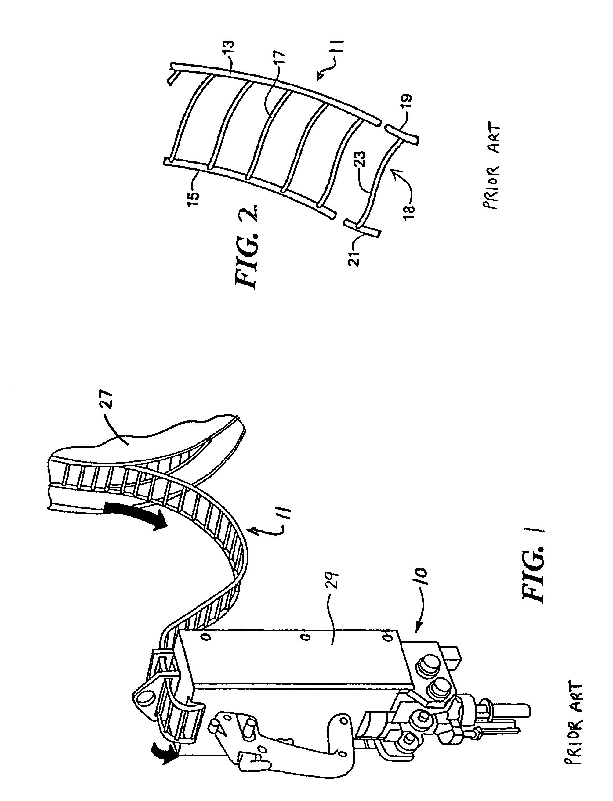
[0036]Referring now to FIG. 1, there is shown a prior art device for dispensing individual plastic fasteners from a supply of continuously connected ladder stock, said device being identified generally by reference numeral 10 and said ladder stock being identified generally by reference numeral 11. As can be appreciated, device 10 can be used in an automated packaging line, for example, to secure together two or more products, such as socks, gloves, towels or other similar items, using one or more plastic fasteners from ladder stock 11.

Continuous Supply of Ladder Stock 11

[0037]Continuous supply of connected ladder stock 11 represents any well known continuous supply of plastic fasteners. For example, ladder stock 11 (also referred to herein as fastener stock 11) may be of the type described in U.S. Pat. No. 4,039,078 to A. R. Bone or of the type described in U.S. Pat. No. 5,615,816 to C. L. Deschenes et al., both of said patents being incorporated herein by reference. As an example,...


PUM


Abstract

A device for dispensing an individual plastic fastener from a supply of fastener stock to couple together two or more objects. The supply of fastener stock includes a plurality of equidistantly spaced cross links which are coupled at one end to a continuous side rail. The fastener dispensing device includes a hollowed sharpened needle shaped to define a longitudinal bore and a feed mechanism for advancing the continuous side rail of the fastener stock into direct axial alignment behind the longitudinal bore of the hollowed needle. The feed mechanism includes a rotatably mounted feed shaft, a pair of feed wheels fixedly mounted on the feed shaft, each feed wheel comprising a plurality of sprockets which are sized and shaped to engage the supply of fastener stock, and first and second clutch wheels which are releasably matingly engageable with one another, the first clutch wheel being fixedly mounted on the feed shaft and the second clutch wheel being rotatably mounted on the feed shaft, each of the first and second clutch wheels including a plurality of ratchets. As a feature of the invention, the number of ratchets on each clutch wheel is at most equal to the number of sprockets on each feed wheel.

Description

BACKGROUND OF THE INVENTION[0001]The present invention relates generally to plastic fasteners and more particularly to devices used in the dispensing of plastic fasteners.[0002]In U.S. Pat. No. 4,039,078 to A. R. Bone, which is incorporated herein by reference, there are disclosed several different types of plastic fasteners (also commonly referred to in the art as plastic attachments). Each plastic fastener described in the patent is manufactured in an H-shaped configuration, with two shortened parallel cross-bars, or T-bars, being interconnected at their approximate midpoints by a thin, flexible filament which extends orthogonally therebetween. Each type of plastic fastener represented in the patent is shown as being fabricated as part of continuously connected ladder stock. In each instance, the ladder stock is formed from two elongated and continuous plastic side members, or rails, which are coupled together by a plurality of plastic cross links, or filaments, the cross links pr...

Claims


Application Information

Patent Timeline
Patent Type & Authority Patents(United States)
IPC IPC(8): B65H5/28
CPCB65C7/00B65C7/006
Inventor FLANNERY, STEVEN E.
Owner AVERY DENNISON CORP
Why Eureka
Try Eureka