Multi-purpose airship

a multi-purpose, airship technology, applied in the direction of lighter-than-air aircraft, weapons launch, transportation and packaging, etc., can solve the problems of less availability, high manufacturing and maintenance costs, and large energy consumption and operation costs, and achieve the effect of less maintenance costs

Inactive Publication Date: 2006-05-02
BUNDO MUTSURO
View PDF2 Cites 20 Cited by
  • Summary
  • Abstract
  • Description
  • Claims
  • Application Information

AI Technical Summary

Benefits of technology

[0009]In view of the above-mentioned problem in the prior art airship, airplane and helicopter, it is an object of the present invention to provide a multi-purpose airship that is usable for multi-purposes with less maintenance cost.
[0014]According to the multi-purpose airship of the present invention, the balloon is made detachable. Thereby, the balloon to be fitted can be selected from those made of an appropriate material, made in an appropriate shape and / or applied with an appropriate marking according to the purpose of use. Also, if the airship is to be used for a high speed flying as a transportation means, the balloon can be detached so that the high speed flying becomes possible.
[0017]In the multi-purpose airship according to the present invention, the main part of the lifting force can be given by the balloon that is filled with the gas lighter than air. Hence, the operation cost becomes less. If the lifting force is insufficient, the fitting angle of the rotor blades of the up and down plural stages is controlled so as to generate an upward thrust so that the lifting force can be made up. If a further larger lifting force is needed, the direction of the propulsion device comprising the plural propeller devices fitted to the distal end portion of the stabilizing wing on each side of the cabin is controlled so as to generate an upward thrust and thereby the necessary lifting force can be obtained.
[0018]Also, in the multi-purpose airship according to the present invention, if the airship is to be propelled, the fitting angle of the rotor blades of the up and down plural stages is controlled so as to generate a propulsive thrust so that the necessary propulsive force can be obtained. If a larger propulsive force beyond the thrust of the rotor is needed, the direction of the propulsion device fitted to the distal end portion of the stabilizing wing is controlled so as to generate a propulsive thrust. Thus, by using the propulsive force generated by both of the rotor and the propulsion device, a high speed flying becomes possible and an emergency case including a first aid can be dealt with.
[0019]While the airship of the present invention is being propelled, a lift is generated by the stabilizing wing and thereby a stability of attitude of the airship can be maintained. Also, by fitting the plural propulsion devices to the distal end portion of the stabilizing wing, a large propulsive force and lifting force can be obtained.

Problems solved by technology

Hence, there is a problem that their area of use is limited to thereby invite a less availability as well as a high cost of manufacture and maintenance.
The airships of these examples are remotely operated unmanned airships of medium size or small size that are provided with the balloon for continuously obtaining a lifting force, so that their area of use is limited to a show event, advertisement, amusement or the like and by no means appropriate for a life saving, exploration, transportation or the like.
In the airplane and helicopter, however, an engine is used as a power source for both of the lifting force and the propulsive force, so that energy consumption is large and operation cost is also large.
As mentioned above, in the prior art airship, airplane and helicopter, there is a problem that their area of use is limited to lead to a less availability and this invites a high cost of manufacture and maintenance.

Method used


Image

  • Multi-purpose airship
  • Multi-purpose airship
  • Multi-purpose airship

Examples


first embodiment

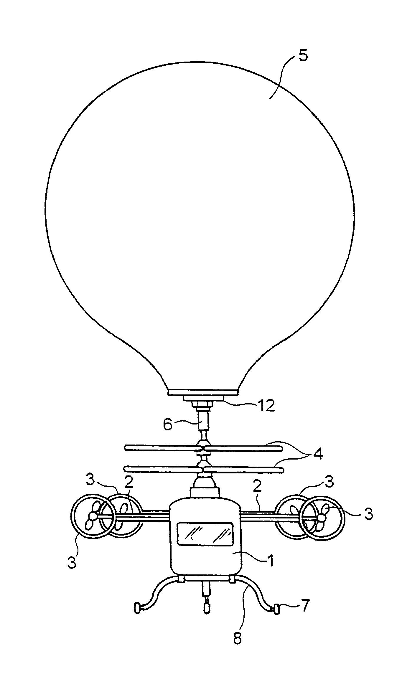
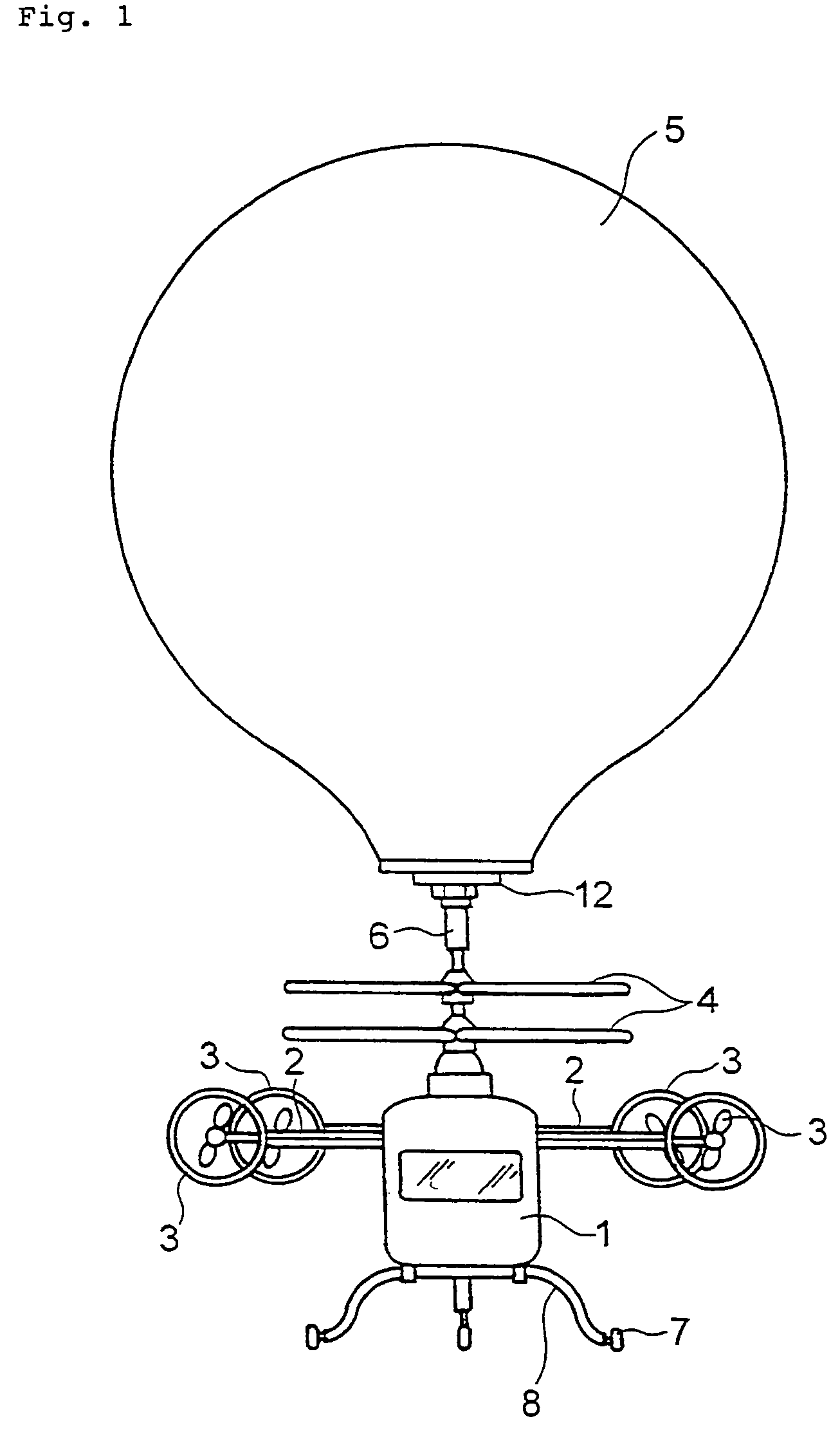
[0026]A multi-purpose airship of a first embodiment will be described with reference to FIG. 1. In FIG. 1, numeral 1 designates a cabin that comprises, like in a usual airplane or helicopter, an entrance through which an operator gets on or gets off, a loading / unloading port through which articles are loaded or unloaded and a seat on which the operator sits as well as comprises a window through which the operator sees the outside scene. A stabilizing wing 2 is fitted to each side of the cabin 1 so as to elongate therefrom substantially horizontally in the rightward and leftward directions as shown in FIG. 1. While flying, the stabilizing wing 2 functions to generate a lift so as to maintain a stability of attitude of the airship. A propulsion device 3 is detachably fitted to a distal end portion of each of the right-hand side and left-hand side stabilizing wings 2. The propulsion device 3 is fitted so that a thrust direction thereof can be adjusted between the horizontal direction a...

second embodiment

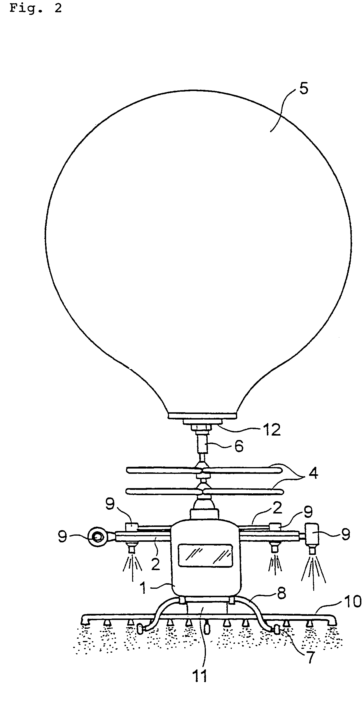
[0039]A multi-purpose airship of a second embodiment will be described with reference to FIG. 2. In FIG. 2, numeral 9 designates a jet engine that is provided in place of the propeller device as the propulsion device 3 of the first embodiment shown in FIG. 1. Like in the case of the first embodiment, the jet engine 9 is detachably fitted to each of the stabilizing wings 2 so as to be replaceable with other propulsion devices. The jet engine 9 is fitted so that a thrust direction thereof can be adjusted to be directed between the horizontal direction and the vertical direction.

[0040]The airship illustrated in FIG. 2 has two jet engines 9 fitted to a distal end portion of each of the stabilizing wings 2 but the construction may also be made such that one jet engine 9 or three or more jet engines 9 are provided to the distal end portion of each of the stabilizing wings 2 so that a lifting force and propulsive force of needed magnitude according to the purpose of use can be obtained.

[00...


PUM


Abstract

A multi-purpose airship usable for multi-purposes with less maintenance cost is provided. The multi-purpose airship comprises an operator cabin (1) to which a work device of agricultural chemical scattering device (10) or the like is fittable, a rotor (4) fitted to a top of the operator cabin (1) and having rotor blades of plural stages (or coaxial rotors) of which fitting angle (or pitch) is adjustable to generate a lifting force and propulsive force, a balloon (5) detachably fitted to a top of the rotor (4) and filled with gas lighter than air to generate a lifting force, a stabilizing wing (2) elongating horizontally from each side of the operator cabin (1) and a propulsion device (3) comprising a propeller device or jet engine fitted to a distal end of the stabilizing wing (2) to vary a thrust direction between the horizontal direction and the vertical direction.

Description

BACKGROUND OF THE INVENTION[0001]1. Field of the Invention[0002]The present invention relates to a multi-purpose airship constructed to be usable for various purposes, such as for an amusement, home use, commercial use, life saving, photographing, exploration, transportation, etc.[0003]2. Description of the Prior Art[0004]In the prior art, while there are proposed various airships, airplanes, helicopters, etc. for various purposes, such as for a life saving, photographing, agricultural chemical scattering, fire fighting, amusement, etc., these means are developed for the respective separate purposes. Hence, there is a problem that their area of use is limited to thereby invite a less availability as well as a high cost of manufacture and maintenance.[0005]As examples of a prior art airship, the Japanese laid-open patent application 1987-18397 discloses a remote operated airship comprising a balloon filled with gas lighter than air and propeller devices of two kinds, one for propulsi...

Claims


Application Information

Patent Timeline
Patent Type & Authority Patents(United States)
IPC IPC(8): B64B1/20B64B1/02B64B1/22B64B1/28B64B1/34B64D1/18
CPCB64B1/02B64B1/22B64D1/18B64B1/34B64B1/28
Inventor BUNDO, MUTSURO
Owner BUNDO MUTSURO
Why Eureka
Try Eureka