Adverse weather headlamp system

a headlamp and reverse weather technology, applied in vehicle interior lighting, transportation and packaging, light and heating equipment, etc., can solve the problems of reducing the visibility range of the driver, reducing the range of the driver's automobile headlamp assembly, and reducing the range of the driver's visibility, so as to prevent foreground glare, and reduce the amount of light emitted

Inactive Publication Date: 2006-05-02
GM GLOBAL TECH OPERATIONS LLC
View PDF21 Cites 16 Cited by
  • Summary
  • Abstract
  • Description
  • Claims
  • Application Information

AI Technical Summary

Benefits of technology

[0006]In another embodiment, the adverse weather headlamp system can comprise two headlamp assemblies, each having a high beam compartment and a low beam compartment. The low beam compartments of the front lamp assemblies can contain a foreground shield in order to reduce the amount of light emitted in the low beam setting to prevent foreground glare. Alternatively, only the driver's side front lamp assembly's low beam compartment will contain at least one foreground shield.
[0007]In another embodiment, the adverse weather headlamp system can comprise two high beam / low beam projector headlamp assemblies. In these high beam / low beam projector headlamp assemblies, the foreground shield is moveable between a blocking position and a pass-through position. The headlamp assemblies of this embodiment also have a cutoff shield that is moveable between a blocking position and a pass-through position. The “high beam” setting and / or beam pattern allows the driver to increase the amount of light projected on the road in order to increase visibility. In the high beam setting, the cutoff shield and foreground shield are in a position that does not block any light (i.e. the pass-through position). An actuator, such as a stepper motor and / or a solenoid, moves the foreground shield and cutoff shield in between each of their pass-through and blocking positions, respectively. The actuator will be connected to a power source and an operating mechanism that allows the driver to move the cutoff shield and foreground shield in order to switch between the high beam, low beam and reduced low beam settings. As used herein, the term “reduced low” beam setting and / or pattern refers to the setting of a headlamp system that reduces the amount of light emitted from the headlamp system in its low beam setting, so that the headlamp system reduces foreground glare during wet, snow-covered or icy road conditions while still providing enough light for a driver to see the road.

Problems solved by technology

While designers of automatic headlamp assemblies have focused on the reduction of glare that blinds oncoming drivers (referred to as disability glare and discomfort glare), foreground glare continues to be a prevalent problem for automotive headlamp assemblies.
Foreground glare refers to light that reflects back into the driver's eyes off of snow-covered and / or icy roads and reduces the range of visibility of the driver so that he / she cannot see the road.
During snow-covered and / or icy road conditions, this emitted light will reflect off the road and result in a dangerous condition where light from the lamp assembly causes foreground glare that reduce the range of visibility of the driver of the automobile.
Moreover, during wet road conditions, the emitted light will reflect off the road and blind oncoming drivers.
While this structure reduces foreground glare, it decreases the amount of light available for the driver to see the road.
In most cases, this reduction in the amount of light available to the driver is greater than is necessary and inhibits the driver's ability to see the road.
Further, when the roads are dry and foreground glare is not a problem, foreground shield 22 remains in place and further hinders the driver's ability to see the road.

Method used


Image

  • Adverse weather headlamp system
  • Adverse weather headlamp system
  • Adverse weather headlamp system

Examples


Embodiment Construction

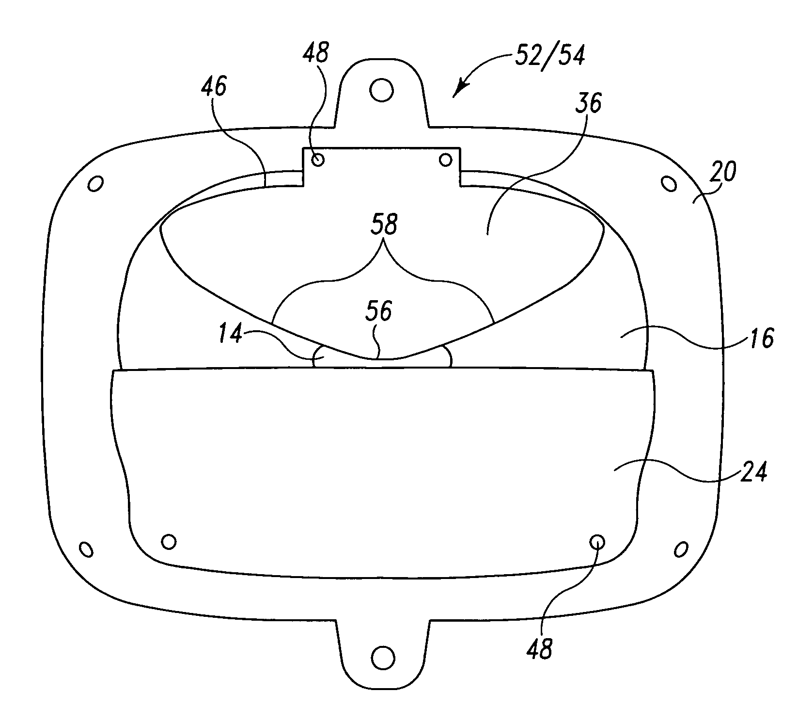
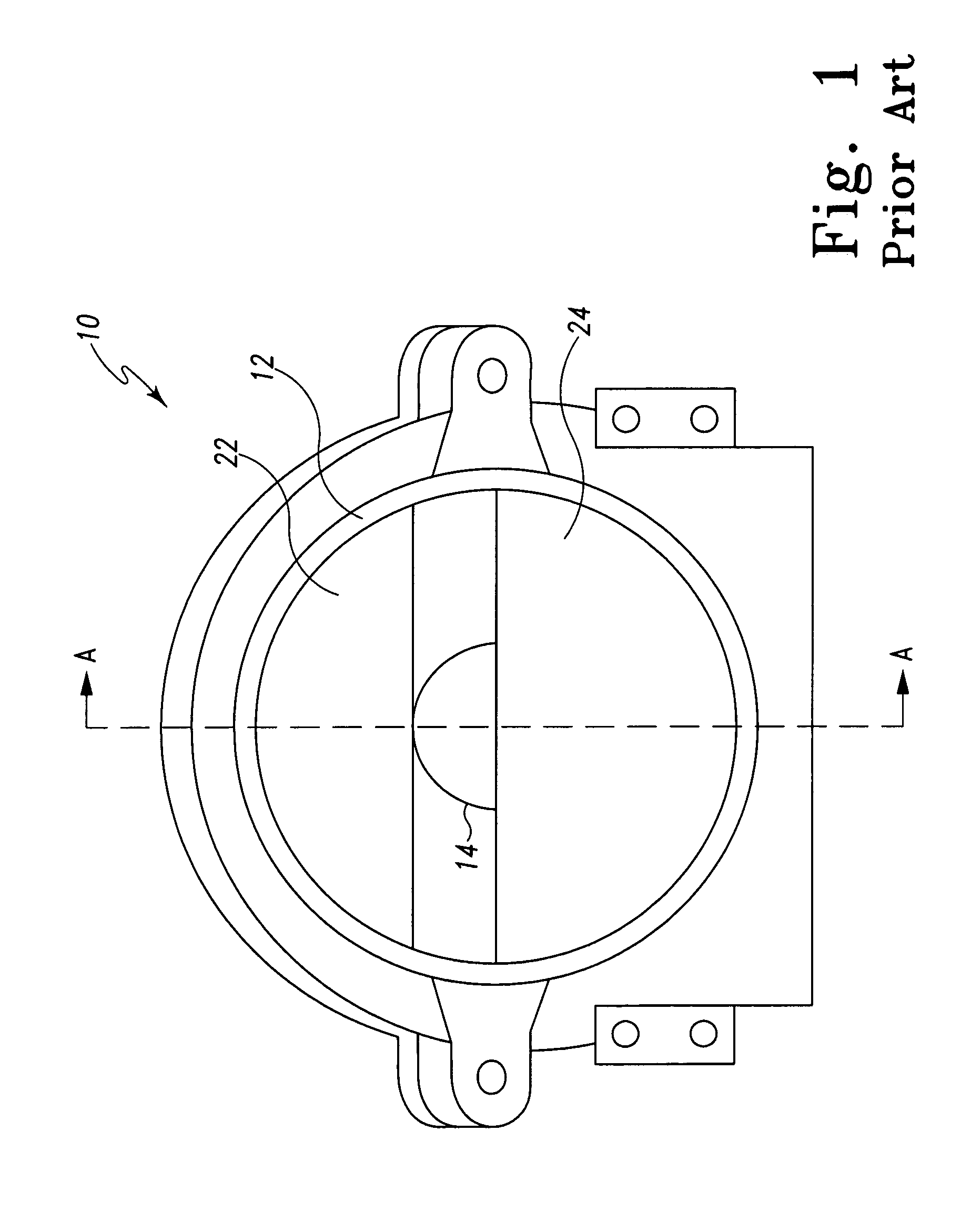
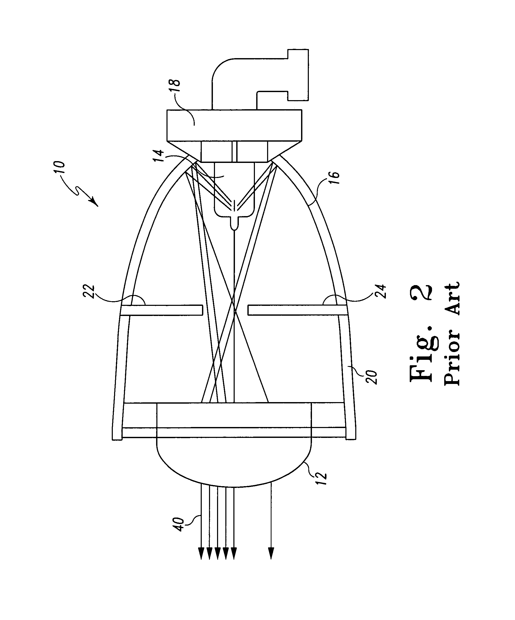
[0020]The embodiments of the adverse weather headlamp system described herein comprises many of the same components as the typical front lamp assembly 10 of FIGS. 1 and 2. Accordingly, many of the same reference numbers are used in FIGS. 3–7 as were used in FIGS. 1–2. FIG. 3a shows a perspective view of an automobile 34 with an adverse weather headlamp system 28. As shown in FIG. 3a, this embodiment comprises two high / low beam lamp assemblies 50, a driver's side driving lamp 52 and a passenger side driving lamp 54. By either providing power to the high / low beam lamp assemblies 50 or to the driving lamps 52 and 54 the driver can switch between a high or low beam or a reduced low beam setting. Both the high / low beam lamp assemblies 50 and driving lamps 52 and 54 are projector headlamp assemblies.

[0021]FIG. 4 shows a cross-sectional view of driver's side driving lamp 52 along line B—B of FIG. 3a. As shown in FIG. 4, driver's side driving lamp comprises light source 14 located behind ex...


PUM


Abstract

An adverse weather headlamp assembly that comprises a foreground shield with two sides that taper up from a bottom portion to form a triangular shaped shield. The foreground shield can be movable between a blocking position and a pass-through position. In combination with a cutoff shield, the foreground shield reduces the amount of emitted light that can be reflected off of a wet or icy road in adverse weather conditions in order to reduce glare, while still allowing enough light to be emitted for the driver to adequately see the road.

Description

BACKGROUND OF THE INVENTION[0001]Various types of glare are produced by an automotive headlamp assembly. While designers of automatic headlamp assemblies have focused on the reduction of glare that blinds oncoming drivers (referred to as disability glare and discomfort glare), foreground glare continues to be a prevalent problem for automotive headlamp assemblies. Foreground glare refers to light that reflects back into the driver's eyes off of snow-covered and / or icy roads and reduces the range of visibility of the driver so that he / she cannot see the road. Foreground glare also refers to the light that reflects off of wet roads and blinds oncoming drivers.[0002]FIG. 1 shows a front view of a typical front lamp assembly 10 that comprises a light source 14. FIG. 2 shows a cross-sectional view of front lamp assembly 10 along line A—A. As shown in FIGS. 1 and 2, a light source 14 is positioned behind a condensing lens 12. Light source 14 is positioned at a first focal point within a t...

Claims


Application Information

Patent Timeline
Patent Type & Authority Patents(United States)
IPC IPC(8): B60Q1/00B60Q1/08B60Q1/14B60Q1/18F21V11/16F21V14/08
CPCB60Q1/14B60Q1/18F21S48/1778F21S48/145B60Q2300/312F21S41/43F21S41/689
Inventor FOUST, MONTY H.POWERS, CHRISTOPHER R.WISLER, JAN A.
Owner GM GLOBAL TECH OPERATIONS LLC
Why Eureka
Try Eureka