Pyrometer

Inactive Publication Date: 2006-05-02
OMRON HEALTHCARE CO LTD
View PDF40 Cites 17 Cited by
  • Summary
  • Abstract
  • Description
  • Claims
  • Application Information

AI Technical Summary

Benefits of technology

[0025]With such constitution, calculation of temperature is made according to a status of an object being mea

Problems solved by technology

When a temperature difference is generated in a thermopile sensor itself and a temperature difference is generated between a thermopile casing disposed in front of a thermopile chip and the thermopile chip, the thermopile chip receives infrared rays from the thermopile casing in addition to infrared rays irradiated from an object (eardrum) being measured, whereby there is caused an error that a higher temperature than that of the actual object being meas

Method used


Image

  • Pyrometer
  • Pyrometer
  • Pyrometer

Examples


second embodiment

(Second Embodiment)

[0094]An explanation will be given below to a second embodiment of the invention.

[0095]FIG. 8 shows an outline of an internal construction of an ear type thermometer 100 according to a second embodiment of the invention.

[0096]Since the ear type thermometer 100 is constructed in the same manner as the thermometer 1 according to the first embodiment except that there are not provided the first thermistor and the second thermistor and that a formula for a temperature of an object is correspondingly different from that in the first embodiment, the same reference characters denote the same constituents and an explanation therefor will be omitted.

[0097]First, the measurement principle for the thermometer 100 will be described.

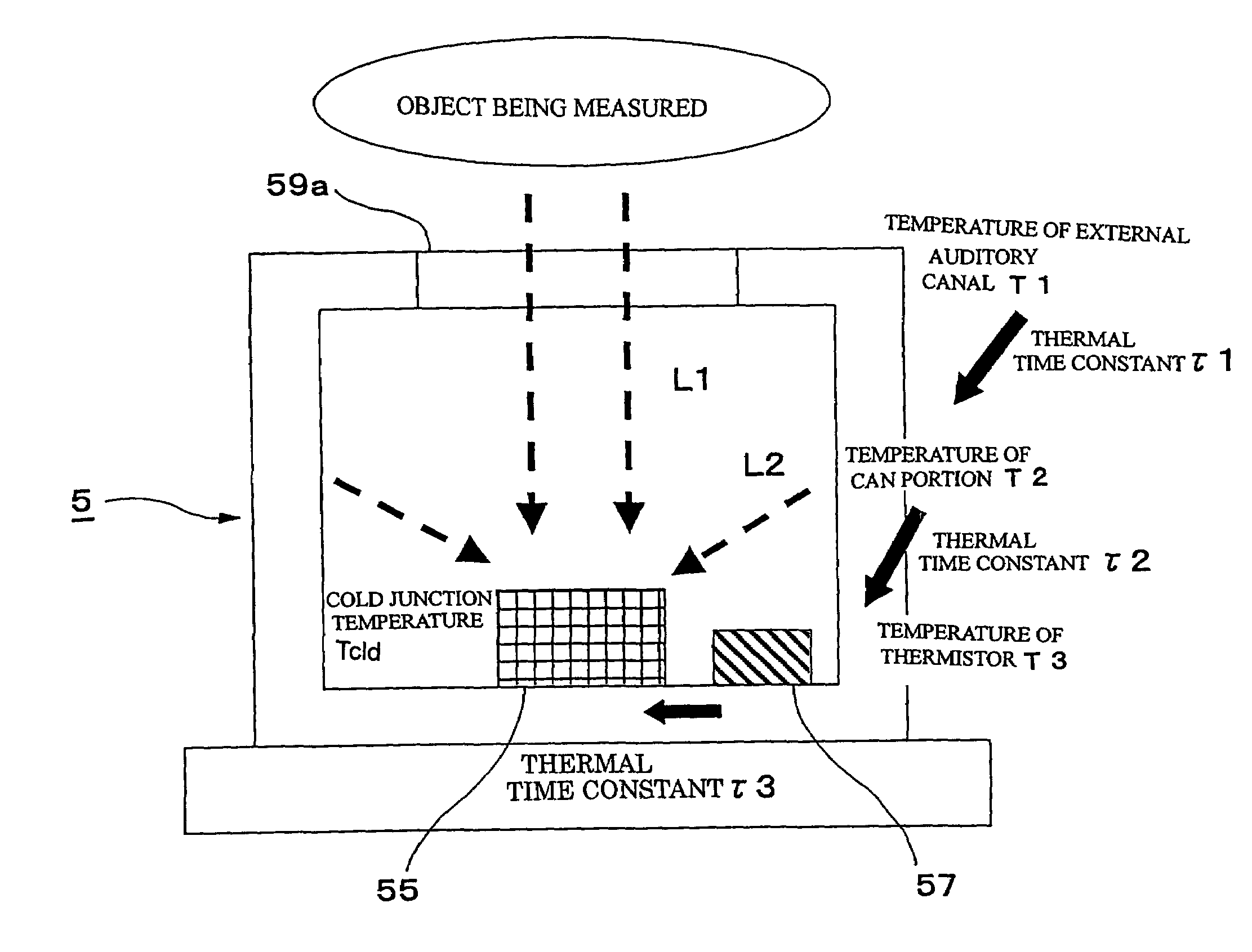
[0098]FIG. 9(a) is a graph showing sampling of temperature changes in a second in an integrated thermistor 57 housed in a thermopile sensor and temperature differences between a tip end of a can portion 59 of a thermopile casing 56 and the integrat...

third embodiment

(Third Embodiment)

[0104]An explanation will be given below to a third embodiment of the invention.

[0105]An internal constitution of an ear type thermometer according to the embodiment is the same as that of the thermometer 100 shown in FIG. 8. The same constituents as those in the first and second embodiments are denoted by the same reference characters, and an explanation therefor will be omitted. In the present embodiment, a feature amount of an object being measured is detected by an integrated thermistor 57 housed in a thermopile sensor 5.

[0106]Assuming that Ta indicates an output of the integrated thermistor 57, Tb indicates a difference information of Ta, and Tc indicates a difference information of Tb, a maximum value of Tc is varied depending upon whether an object being measured, as shown in FIG. 11, is an adult, a child, or a blackbody furnace. Here, FIG. 11 shows the behavior of Tc immediately after a probe 4 is inserted into an ear, where the abscissa represents the numb...

fourth embodiment

(Fourth Embodiment)

[0127]An explanation will be given below to a fourth embodiment of the invention.

[0128]An ear type thermometer according to the embodiment is the same as the thermometer 110 according to the third embodiment. The same constituents as those of the thermometer 110 are denoted by the same reference characters, and an explanation therefor will be omitted.

[0129]The thermometer of this embodiment detects insertion of a probe 4 into an ear, and temperature information of an integrated thermistor 57, respective constituent members of the probe 4, and a thermopile chip 55 when such insertion is detected is made an initial value, and changes from the initial value are used to continuously correct an output of the thermopile chip 55.

[0130]FIG. 17 shows the procedure of measurement of body temperature performed by the thermometer.

[0131]First, when power is turned on (STEP 31), A / D conversion of a signal from the thermistor 57 and a signal from the thermopile chip 55 is starte...


PUM


Abstract

A first thermistor 8 and a second thermistor 9 are arranged forwardly and rearwardly of a thermopile sensor 5. A thermopile chip 55 is arranged and interposed between the first thermistor 8 and an integrated thermistor 57. A sensor cover is mounted in contact with front and side portions of a can portion 59 of a thermopile casing 56. A temperature or a radiant quantity of infrared rays on the front portion of the can portion is estimated from a temperature change of the integrated thermistor per second.

Description

TECHNICAL FIELD[0001]The present invention relates to a radiation thermometer for measuring a temperature of an object being measured, by measuring infrared rays irradiated from the object being measured.BACKGROUND ART[0002]Conventionally, radiation thermometers of this kind calculate a temperature of an object being measured, on the basis of an output of a thermopile and a temperature of a thermopile chip, in accordance with the following formula of principleE=L(Tx4−Ta4)where E: energy (output of a thermopile chip) received by the thermopile chip, L: a coefficient, Tx: temperature of an object being measured, and Ta: temperature of the thermopile chip.[0003]Also, sensors for measuring a radiant quantity of infrared rays include a thermopile sensor generally constructed such that a thermopile chip is bonded to a metallic stem, a window of silicone glass capable of transmitting therethrough infrared rays is provided on a roof panel, and the whole is sealed by a metallic casing.[0004]...

Claims


Application Information

Patent Timeline
IPC IPC(8): G01J5/00A61B5/00G01J5/12G01J5/16
CPCG01J5/02G01J5/021G01J5/025G01J5/026G01J5/045G01J5/049G01J5/12G01J5/16G01J5/522G01J5/04A61B5/01G01J2005/068G01J5/064G01J5/53
Inventor TABATA, MAKOTOOTA, HIROYUKIONISHI, YOSHIHIDEOGURA, TOSHIHIKOSATO, TATSUYASATO, TAIGA
Owner OMRON HEALTHCARE CO LTD
Why Eureka
Try Eureka