Constant current Class 3 lighting system

a lighting system and constant current technology, applied in emergency power supply arrangements, instruments, process and machine control, etc., can solve the problems of significant danger, inflexible and costly steel conduit and whips, required in class 1 systems for safety measures, and time-consuming installation of steel conduit around obstructions, etc., to achieve easy modular connection, increase flexibility in reconfiguration and relocation of lighting fixtures, and facilitate installation

Active Publication Date: 2006-05-02
ISOTERA +1
View PDF4 Cites 29 Cited by
  • Summary
  • Abstract
  • Description
  • Claims
  • Application Information

AI Technical Summary

Benefits of technology

[0011]Each lamp driver is preferably connected to the power supply by a plenum rated Class 3 cable. According to one aspect of the invention, the cable preferably includes a 14 AWG ground and an insolated non-polarized 18 AWG twisted pair. Each cable is also preferably terminated using a self-locking connector to allow for easy modular connection between components of the lighting system. This modular connectivity provides for easier installation as well as increased flexibility in the reconfiguration and relocation of lighting fixtures.
[0012]In comparison to traditional Class 1 lighting systems, the present invention results in electrical energy savings, reduced labor, lowered costs, and additional safety by eliminating the need to run the power line voltage to each light fixture. In addition, unlike previously known high-frequency Class 3 lighting systems, the constant current power supply allows for equal light output regardless of cable length and eliminates the need for expensive matching circuitry in the lamp driver. Lastly, the heat dissipation focused at the power supply can be flexibly located within a building ceiling spaces away from the fixture to reduce the load demands of the HVAC system.

Problems solved by technology

As a regular power line is not power limited and is considered large enough to be a fire-hazard, the National Electrical Code classifies traditional lighting systems as Class 1 circuits and thus requires numerous protective measures.
First, by delivering a line voltage to each fixture, traditional lighting systems provide a shock hazard and thus present a significant danger during installations.
In addition, components such as steel conduit and whips, which are required in Class 1 systems for safety measures, are both costly and inflexible.
For example, installation of steel conduit around obstructions can be time-consuming, and any last-minute reconfigurations may become very cumbersome.
Because of the Class-3 output characteristics of the power supply units, the amount of available power in the Nilssen patent was limited to a level considered acceptably safe from a fire initiation viewpoint, yet adequate in power to provide ample light from a fluorescent lighting fixture (e.g. 100 Watts).
However, the Nilssen lighting system did not provide a complete answer.
This approach results in a significant voltage drop along transmission cables causing the output of a lamp to vary significantly depending on its distance from the power supply.
In addition, fixtures designed to operate with the constant voltage power supply disclosed in the Nilssen patent require matching tank circuits, which may increase both the cost and complexity of the lamp driver circuits.

Method used


Image

  • Constant current Class 3 lighting system
  • Constant current Class 3 lighting system
  • Constant current Class 3 lighting system

Examples


Embodiment Construction

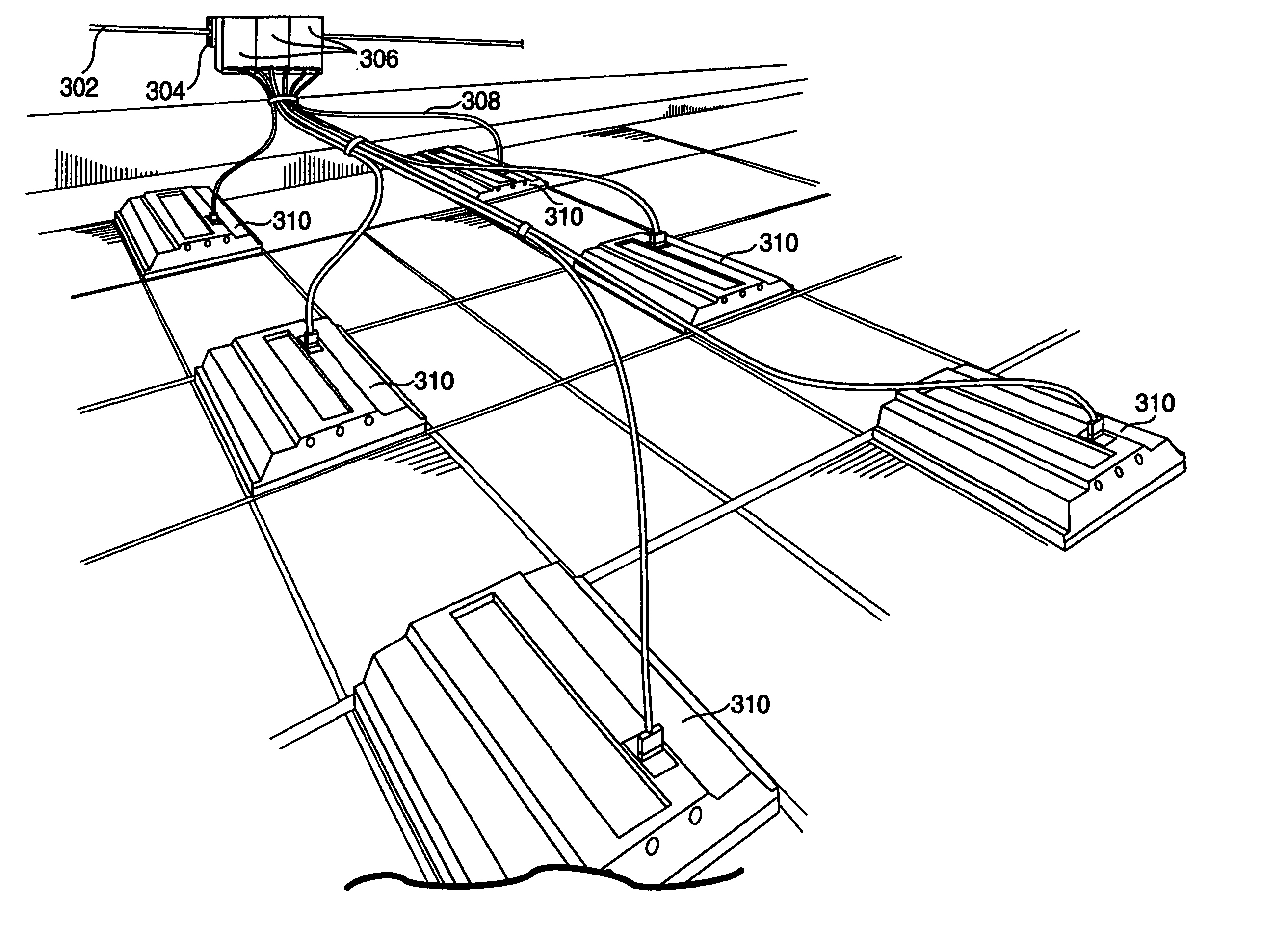
[0025]The present invention is a lighting system having a power supply, at least one luminaire, and a flexible cable for connecting the power supply to the luminaires. The power supply preferably includes a power supply input to receive a power line signal, a circuit to convert the power line signal to a substantially constant-current, high-frequency signal, and a power supply output to output the substantially constant-current, high-frequency signal. Each luminaire also preferably includes a lamp, a housing to hold the lamp, luminaire input to receive the high-frequency signal from the power supply, and a lamp driver circuit configured to use the received output signal to operate the lamp.

[0026]FIG. 3 shows one exemplary embodiment of the lighting system. In this embodiment, a junction box 304 is supplied with a power line signal (typically, either a 60 Hz@120V or 277V signal) through a pair of power line conductors and a safety ground via a steel armored conduit 302. In the depict...


PUM


Abstract

A lighting system having a power supply and at least one luminaire. The power supply includes a power supply input to receive a first signal having a first frequency and a circuit for converting the first signal to a second signal. The power supply also includes at least one power supply output to output a second signal having a substantially constant current and a second frequency distinctly higher than the first frequency. The luminaire includes a lamp coupled to a lamp driver circuit, which has an input for receiving the output signal from the power supply and which is configured to use the received output signal to operate the lamp. The lamp driver input and the power supply output may be connected by a flexible cable.

Description

BACKGROUND[0001]The National Electrical Code defines three classes of circuits and provides specific installation requirements for each. In general, Class 2 is defined as any circuit that provides 30V or less at 100 VA. Class 3 is defined as any circuit that provide up to 150V at 100 VA. Class 1 may then be used to classify circuits that provide output that is not power limited.[0002]Lighting systems typically consist of permanently wired-in lighting fixtures, with each lighting fixture obtaining its power directly from a regular Class 1 power line. As a regular power line is not power limited and is considered large enough to be a fire-hazard, the National Electrical Code classifies traditional lighting systems as Class 1 circuits and thus requires numerous protective measures. For example, traditional lighting systems are required by the National Electrical Code to have electrical conductors that are installed in the form of armored cable or within steel conduits.[0003]FIGS. 1 and...

Claims


Application Information

Patent Timeline
Patent Type & Authority Patents(United States)
IPC IPC(8): G05F1/00
CPCH05B41/245H02J3/10
Inventor RIMMER, PHILIP JOHNSHERRINGTON, CAROLE FRANCES
Owner ISOTERA
Why Eureka
Try Eureka