Optimization of a loop antenna geometry embedded in a wristband portion of a watch

a technology of loop antenna and wristband, which is applied in the direction of loop antenna, antenna supports/mountings, electrical appliances, etc., can solve the problems of complex and bulky, difficult to design a mechanism that provides favourable operation, and significant antenna loss

Inactive Publication Date: 2006-05-02
ETA SA MFG HORLOGERE SUISSE
View PDF28 Cites 21 Cited by
  • Summary
  • Abstract
  • Description
  • Claims
  • Application Information

AI Technical Summary

Problems solved by technology

Consequently it is difficult to design a mechanism that provides favourable operation, as this part is prone to break down.
A solution consisting in providing wireless instrument 100 with an additional apparatus for compensating changes in antenna gain and resonance frequency resulting from changes in the antenna's loop length, is complex and bulky, which is not desirable in such wireless instruments.
Thus, although resulting radiating surface RS1+RS2 increases slightly, in the meantime antenna losses increase significantly because they depend on the antenna inductance which increases with the total length of the radiating element, and then overall antenna efficiency is significantly reduced.
Alternative solutions that would consist in replacing the U-shaped antenna with a multi-loop antenna, is not desirable because manufacturing process of such multi-turn antennas is more difficult.

Method used


Image

  • Optimization of a loop antenna geometry embedded in a wristband portion of a watch
  • Optimization of a loop antenna geometry embedded in a wristband portion of a watch
  • Optimization of a loop antenna geometry embedded in a wristband portion of a watch

Examples


Embodiment Construction

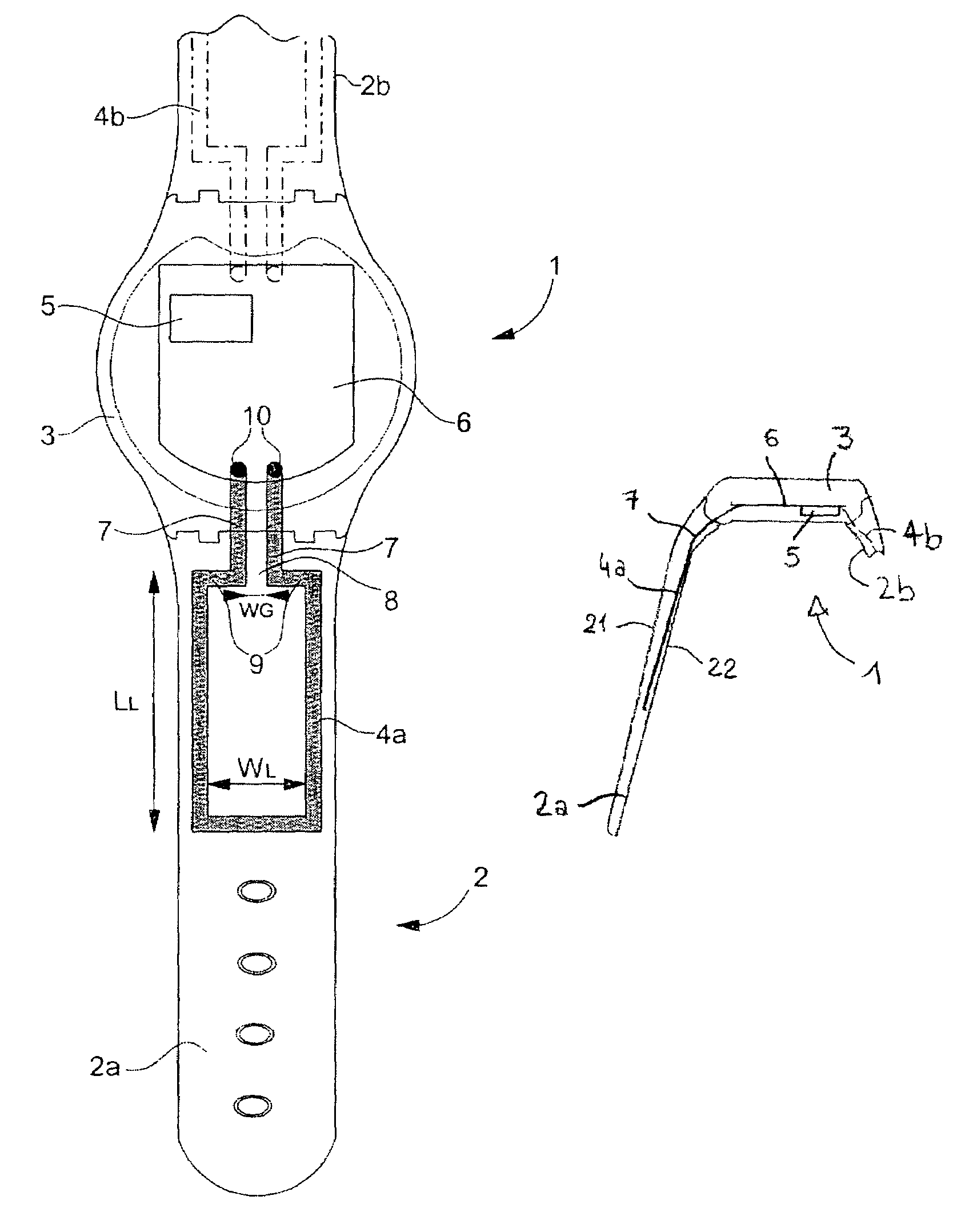
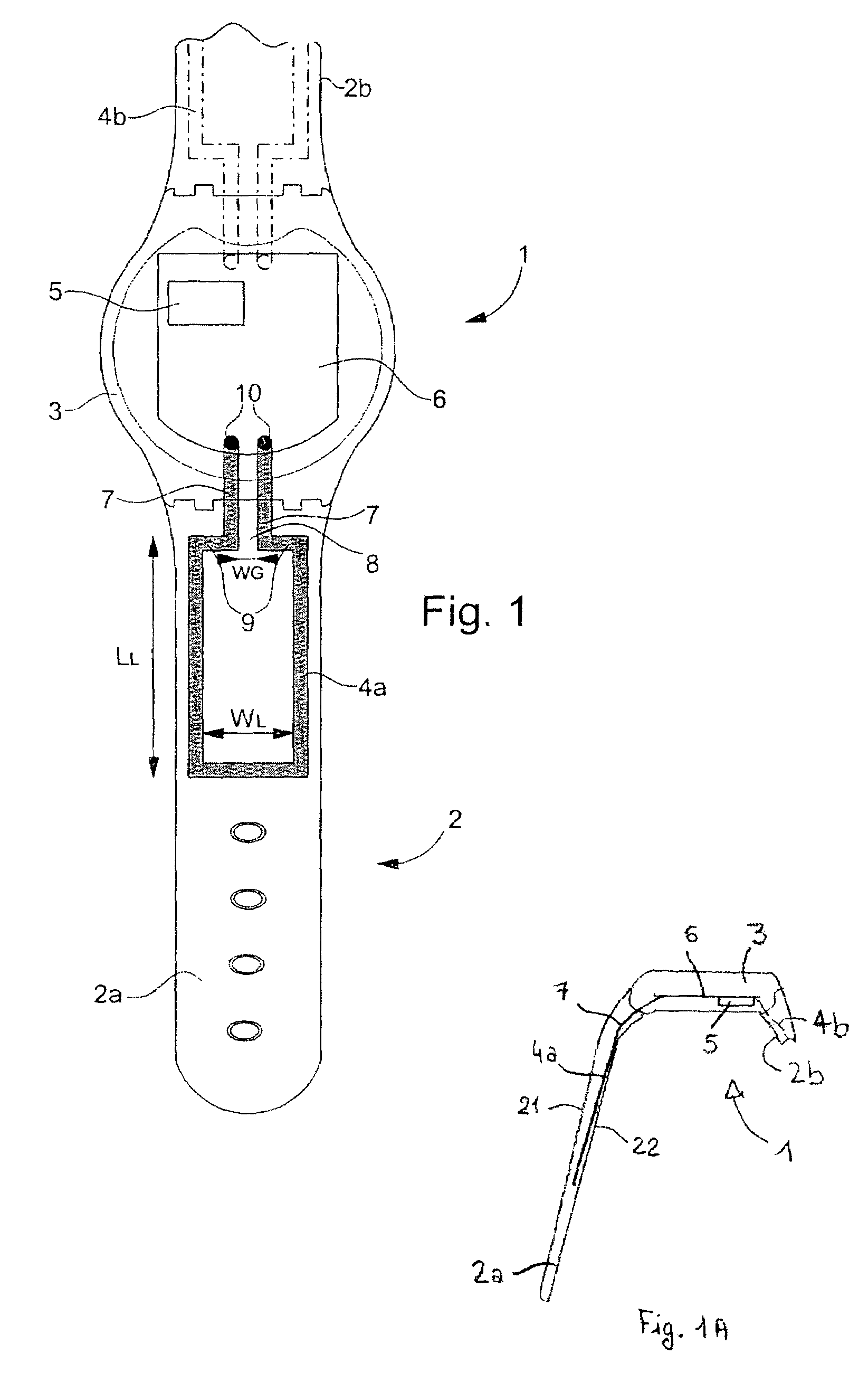
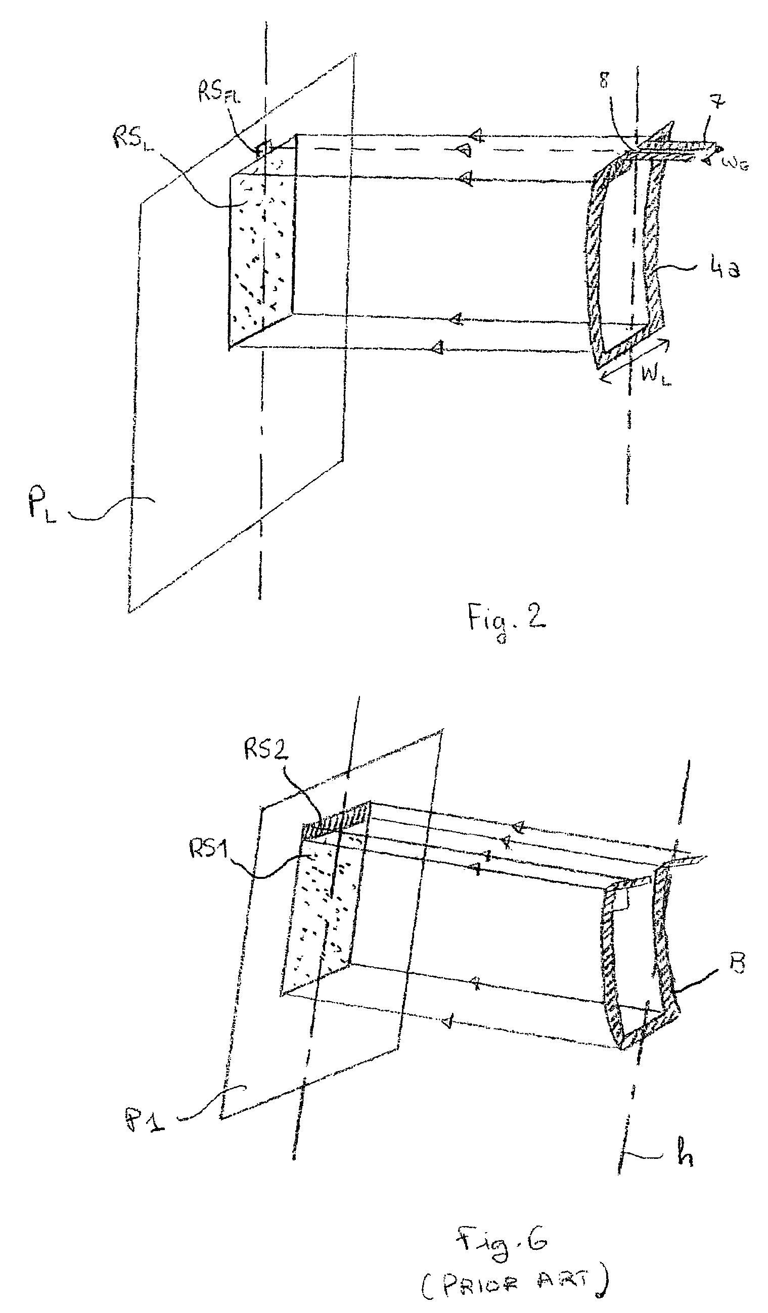
[0023]As already mentioned herein before, the present invention concerns wrist-carried wireless instrument for receiving radio frequency signals, in the frequency band from 30 to 300 MHz and preferably in the frequency band from 88 to 108 MHz using the radio data transmission system. The invention more particularly relates to an antenna structure having optimised antenna efficiency, and in particular, an optimised geometry in order to obtain a good compromise between, on the one hand, the antenna radiating surface, and on the other hand, the antenna losses.

[0024]Referring first to FIG. 1, a cross-sectional view of a wrist-carried wireless instrument is shown according to a preferred embodiment of the invention. Wireless instrument 1 comprises a wristband 2 having a first 2a and a second 2b band portions connected to opposite edges of a casing 3, each band portion having upper and lower surfaces (21 and 22, see FIG. 1A). At least a first single loop antenna 4a is embedded in one band...


PUM


Abstract

The invention relates to a wireless instrument (1) including a wristband (2) having two band portions (2a, 2b) connected to opposite edges of a casing (3), each band portion having upper and lower surfaces (21,22). At least one single loop antenna (4a) is embedded in one band portion and extends between the corresponding upper and lower surfaces. This single loop antenna is connected via feeding lines (7) through one edge of the casing to an antenna receiver (5). The loop antenna and the feeding lines define a radiating element, wherein the feeding lines are arranged so as to be a negligible part of this antenna radiating element.

Description

FIELD OF THE INVENTION[0001]The invention relates to a wrist-carried wireless instrument for receiving signal in the radio frequency range, and more particularly, to a wristwatch receiver having magnetic loop antennas embedded in the wristband. In the following specification, loop antenna has to be understood as one single loop conductor lying substantially in the same plane, the frequency of operation of which is normally such as to give a substantially uniform current along the conductor.BACKGROUND OF THE INVENTION[0002]In recent years, such wireless instruments for receiving radio frequency signals with an antenna system embedded in the wristband have become common. Many prior art solutions disclose an antenna device having a circumferentially variable size, embedded in a wristband, for use with a radio that is worn on the arm of a person. By doing this, the antenna can be made long enough to receive frequency signals beyond the VHF band (30–300 MHz). As shown on FIG. 3, loop ant...

Claims


Application Information

Patent Timeline
Patent Type & Authority Patents(United States)
IPC IPC(8): H01Q7/00H01Q1/12
CPCH01Q7/00H01Q1/273
Inventor BISIG, MARTIN
Owner ETA SA MFG HORLOGERE SUISSE
Why Eureka
Try Eureka