Dual-frequency band and dual round polarization rear radiation spiral antenna

A circularly polarized antenna, dual circularly polarized technology, applied in the direction of antenna, radiating element structure, electrical components, etc. problem, to achieve the effect of improving the caliber utilization rate, good characteristics and simple structure

Active Publication Date: 2008-04-30
BEIJING SATELLITE INFORMATION ENG RES INST
View PDF4 Cites 19 Cited by
  • Summary
  • Abstract
  • Description
  • Claims
  • Application Information

AI Technical Summary

Problems solved by technology

[0002] The backfiring antenna has the characteristics of high gain and so on, and has a wide range of applications, but this type of antenna has the following disadvantages: First, the backfiring antenna is generally single-band, multi-band or wide-band, and the backfiring antenna is generally linearly polarized or Circular polarization, for increasingly tight frequency resources, the antenna itself cannot achieve good polarization isolation
The second is that the backfiring antenna generally adopts a cylindrical reflective cavity, but this conventional reflective cavity cannot guarantee the maximum antenna gain under a given aperture size.
Chinese Patent No.: ZL96108158.9 "Circularly Polarized Backfiring Antenna" discloses a circularly polarized backfiring antenna. The backfiring antenna uses a helical antenna as the primary radiator. The antenna is circularly polarized, but belongs to a single circle Polarized antenna; the frequency band characteristic of the invention is not dual-band

Method used


Image

  • Dual-frequency band and dual round polarization rear radiation spiral antenna
  • Dual-frequency band and dual round polarization rear radiation spiral antenna
  • Dual-frequency band and dual round polarization rear radiation spiral antenna

Examples


Embodiment Construction

[0026] The present invention will be further described below in conjunction with accompanying drawing.

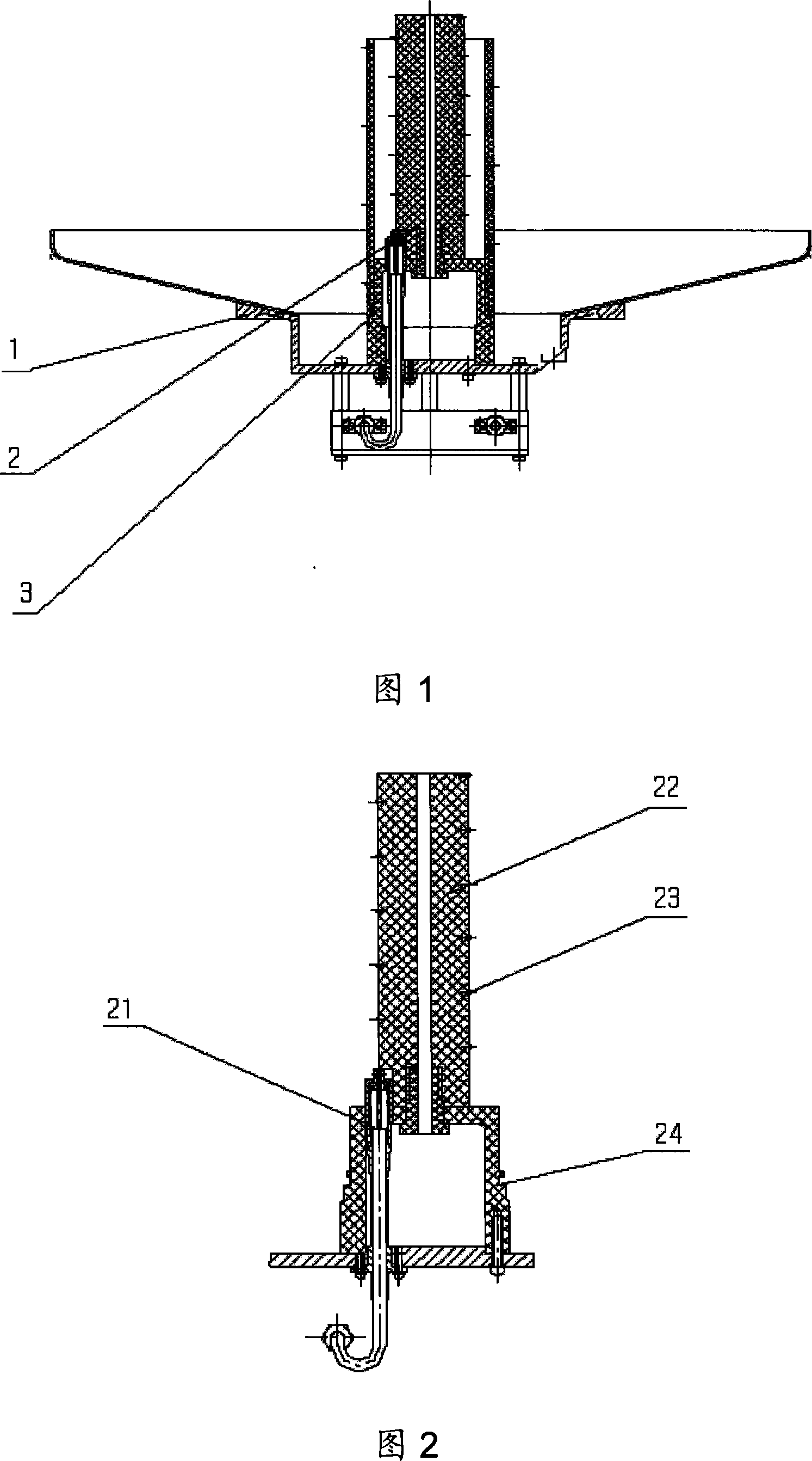
[0027] As shown in Figure 1, the dual-band dual circularly polarized backfiring helical antenna of the present invention is composed of a reflective cavity assembly 1, a high-frequency circularly polarized antenna assembly 2 and a low-frequency circularly polarized antenna assembly 3, and the low-frequency circularly polarized antenna assembly 3 are set outside the high-frequency circularly polarized antenna assembly 2, the two are coaxial, and are installed on the common reflection cavity assembly 1.

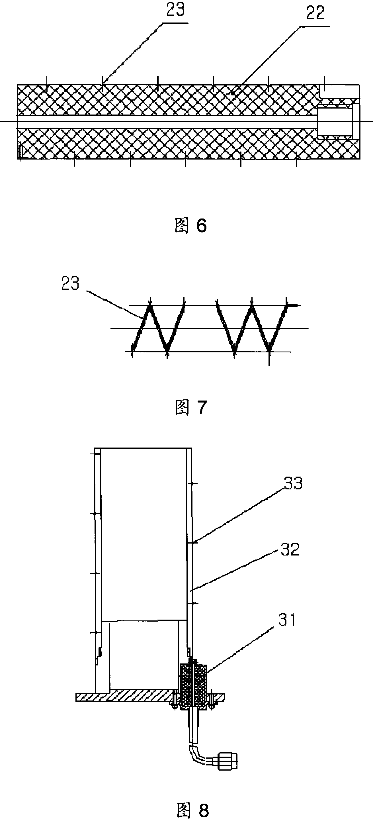
[0028] As shown in FIG. 2 , the high-frequency primary radiator is composed of a first metal helical wire 23 wound left-handedly on the first helical wire dielectric support 22 , and is installed as a whole with the reflective cavity assembly 1 through a bracket 24 .

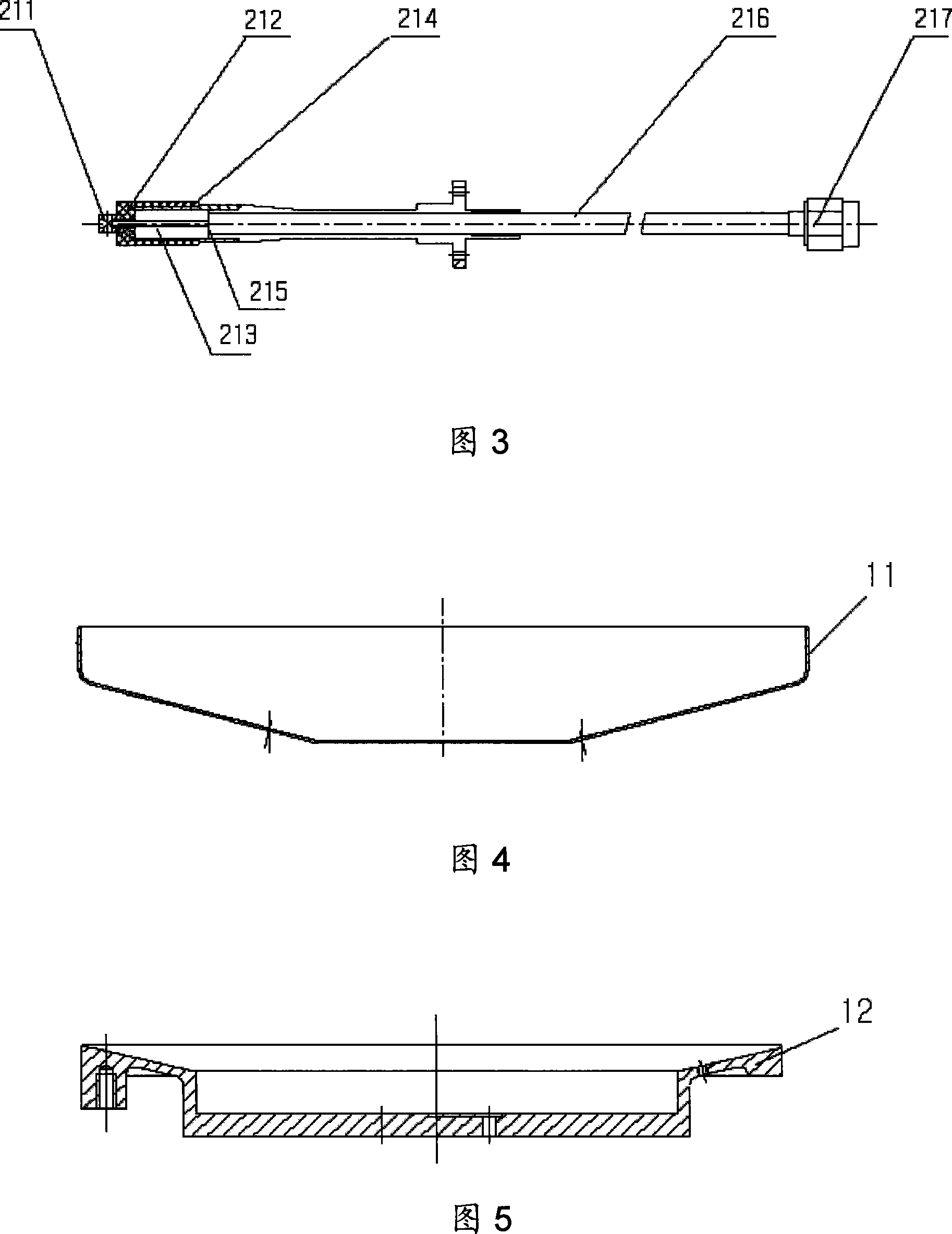
[0029] As shown in Figure 3, the feed assembly 21 of the high-frequency primary radiator consists of a conn...


PUM


Abstract

The invention discloses a double circular polarization backfire antenna for double band, which comprises a high-frequency circular polarization antenna component (2), a low-frequency circular polarization antenna component (3) and a reflecting cavity component (1) mutually used by the two; the high-frequency circular polarization antenna component (2) comprises a high-frequency feeding component (21) and a high-frequency primary radiator; the low-frequency circular polarization antenna component (3) comprises a low-frequency feeding component (31) and a low-frequency primary radiator; the high-frequency and low-frequency feeding components are formed by the metal helical wires twisting on medium supports of the helical wires; the low-frequency circular polarization antenna component (3) is sheathed on the outside of the high-frequency circular polarization antenna component (2), and the two are coaxially fixed on the center position of the reflecting cavity component (1); the rotary directions of the metal helical wires of the high-frequency and low-frequency feeding components are opposite. The reception and transmission of the antenna of the invention separately work in two different bands, and two polarizations of the double circular polarization antenna are perpendicular to each other, thereby increasing the polarization isolation between the two bands and improving the overall performance of the system.

Description

technical field [0001] The invention relates to antenna technology in the field of wireless communication, in particular to a dual-band dual-circularly polarized helical back-firing antenna that is simultaneously applied to reception and transmission. Background technique [0002] The backfiring antenna has the characteristics of high gain and so on, and has a wide range of applications, but this type of antenna has the following disadvantages: First, the backfiring antenna is generally single-band, multi-band or wide-band, and the backfiring antenna is generally linearly polarized or Circular polarization, for increasingly tight frequency resources, the antenna itself cannot achieve good polarization isolation. The second is that the backfiring antenna generally adopts a cylindrical reflection cavity, but this conventional reflection cavity cannot guarantee the maximum antenna gain under a given aperture size. [0003] Chinese Patent No.: ZL93222793.X "A High-Performance S...

Claims


Application Information

Patent Timeline
IPC IPC(8): H01Q19/10H01Q1/36
Inventor 董涛李景贵王兵葛琳
Owner BEIJING SATELLITE INFORMATION ENG RES INST
Why Eureka
Try Eureka