DC offset calibration for a radio transceiver mixer

a radio transceiver and mixer technology, applied in the field of radio frequency transceivers, can solve the problems of non-linear impedance of mos transistors in the linear region, limited linearity of the mixer, and insufficient control of the gain of the mixer, so as to reduce the dc offset

Inactive Publication Date: 2006-05-02
AVAGO TECH WIRELESS IP SINGAPORE PTE
View PDF13 Cites 24 Cited by
  • Summary
  • Abstract
  • Description
  • Claims
  • Application Information

AI Technical Summary

Benefits of technology

[0006]The present invention pertains to a mixer design for radio transceivers, which includes a c

Problems solved by technology

There are certain weaknesses with this design, however.
First, the linearity of the mixer is limited in that the impedance of the MOS transistors in the linear region become non-linear when the gate control voltage varies considerably.
Second, the gain of the mixer is not well controlled, since it is difficult to match the impedance of the MOS transistors in the linear region to that of the resistor in the feedback loop of the amplifier.
Finally, even if additional sets of MOS transistors are included for the DC offset cancellation path, mismatch of the transistors can be of a conc

Method used


Image

  • DC offset calibration for a radio transceiver mixer
  • DC offset calibration for a radio transceiver mixer
  • DC offset calibration for a radio transceiver mixer

Examples


Embodiment Construction

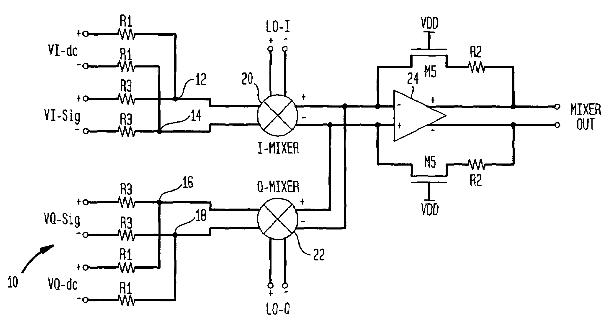
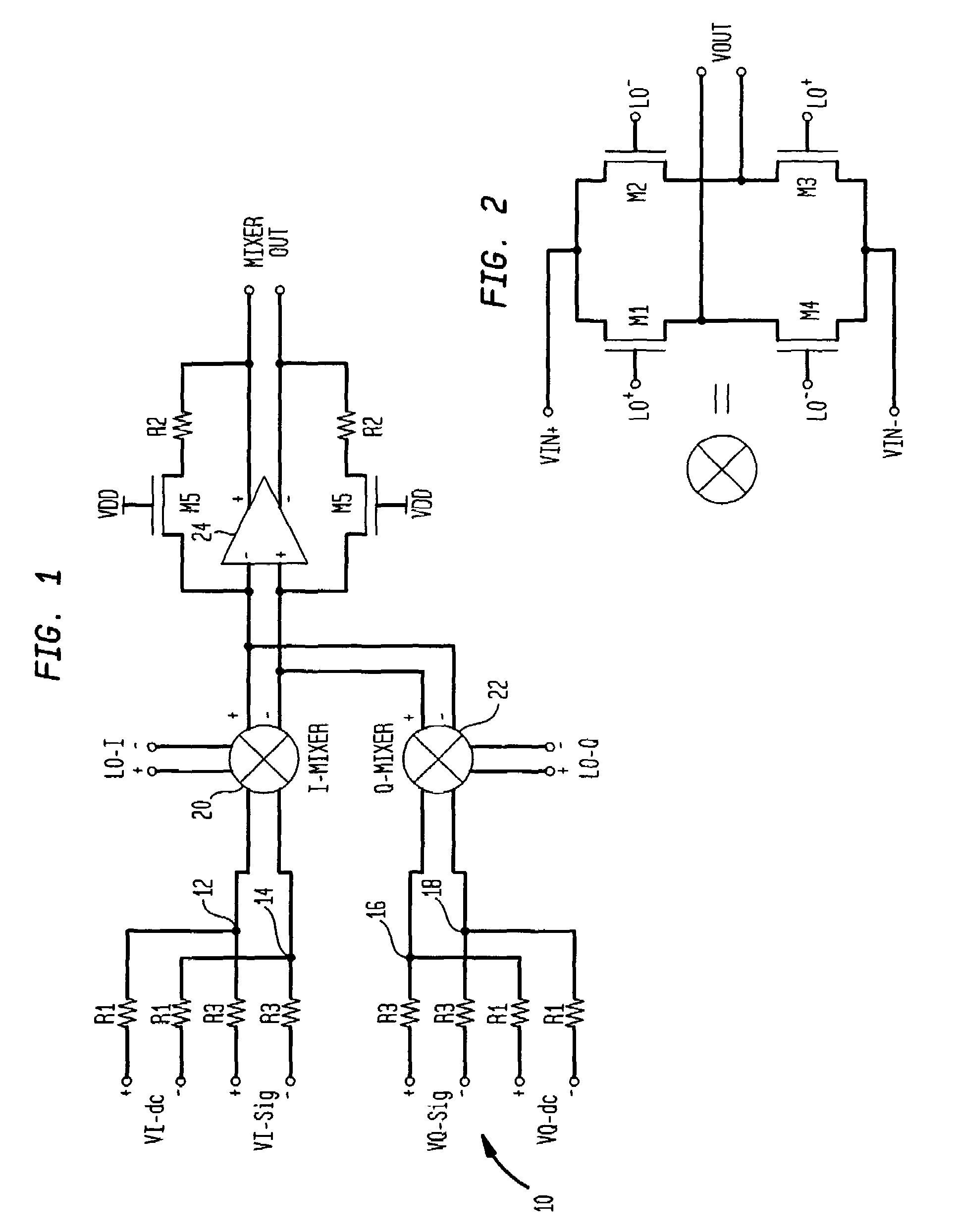
[0018]Referring to FIG. 1, there is shown an exemplary embodiment of an image reject mixer 10 according to an embodiment of the present invention. Resistors R1 (each R1 has the same resistance value) are configured to receive differential offset compensation signals, VI-dc and VQ-dc, and resistors R3 (each R3 has the same resistance value) are configured to receive main signals, VI-sig and VQ-sig, where “I” and “Q” indicate an in-phase channel and an quadrature phase channel, respectively. Unlike the prior art, with the use of the resistors, rather than reliance upon the on resistance of MOS transistors, the linearity of image-reject mixer 10 is superior. Resistors R3 function to convert the signals VI-sig and VQ-sig into currents, and resistors R1 function to convert VI-dc and VQ-dc inot currents, which are summed at nodes 12, 14, 16 and 18. Resistors R1 are selected to provide a DC offset cancellation path. An in-phase commutating mixer switch 20 is configured to receive the diffe...


PUM


Abstract

A mixer for a radio transceiver includes a commutating mixer switch having a first differential input port coupled to a DC offset cancellation path. The first differential input port of the mixer switch includes a first terminal coupled to a first end of a first resistor and a second terminal coupled to a first end of a second resistor. Second ends of the first and second resistors are configured to receive a differential input signal. The DC offset cancellation path may provide a resistively coupled DC calibration signal for reducing the magnitude of DC offsets that may be present at the input of the mixer switch. The concept can be used for either image or non-image reject mixers.

Description

BACKGROUND OF THE INVENTION[0001]This invention relates in general to radio frequency (RF) transceivers and more particularly to mixers used in RF transceivers that provide DC offset calibration.[0002]An RF transceiver (transmitter / receiver) typically requires a frequency translation function, in which a signal is translated from one carrier frequency, ω1, to another frequency, ω2. The translation is carried out by what is known as a “mixer.” In effect, a mixer translates the center frequency, ω1, of a signal band, to a center frequency, ω2, by mixing the signal band with a local oscillator signal having a frequency of ωLO, where ωLO=(ω1−ω2). The mixing operation yields a first band centered around ω2 and a second band centered around 2ω1−ω2. An appropriate filter is then typically employed to select the desired signal band centered around ω2. When ω1>ω2, this operation is known in the art as downconversion mixing. On the other hand, when ω1<ω2, the operation is known as upcon...

Claims


Application Information

Patent Timeline
IPC IPC(8): H04B1/10H04B1/18H03D7/14H04B1/30
CPCH03D7/1441H03D7/1458H03D7/1466H03D7/165H03D7/1483H04B1/30H03D2200/0047H03D2200/0025H03D2200/0043
Inventor SHU, TZI-HSIUNG
Owner AVAGO TECH WIRELESS IP SINGAPORE PTE
Why Eureka
Try Eureka