Metal encaustic tile making machine

Inactive Publication Date: 2006-05-09
CHUANG SEN JUNG
View PDF13 Cites 8 Cited by
  • Summary
  • Abstract
  • Description
  • Claims
  • Application Information

AI Technical Summary

Benefits of technology

[0002]In a conventional metal encaustic tile making machine, a continuous sheet of metal sheet material is delivered forwards at a constant speed to a corrugation forming roller unit for processing into a corrugated metal sheet. When operating the first mold and second mold of the angle forming unit of the encaustic tile making machine to make angles at the corrugated metal sheet, the feeding of the continuous sheet of metal sheet material must be stopped. This metal encaustic tile making procedure is complicated, resulting in low efficiency.
[0003]The present invention has been accomplished under the circumstances in view. It is therefore the main object of the present invention to provide a metal encaustic tile making machine, which eliminates the drawback of the aforesaid prior art design. To achieve this and other objects of the present invention, the metal encaustic tile making machine comprises a machine base, a corrugation forming roller unit adapted to corrugate a continuous sheet of metal sheet material into a corrugated metal sheet, an angle forming unit adapted to stamp the corrugated metal sheet into a metal encaustic tile having angles, a cutting unit adapted to cut the finished metal encaustic tile from the continuous sheet of metal sheet material, two parallel guide rails provided at the machine base, a slide coupled to and movable along the guide rails and carrying the angle forming unit and the cutting unit on the machine base, a transmission screw pivotally mounted in the machine base, a coupling block fixedly provided at a bottom side of the slide and threaded onto the transmission screw, and a reversible motor mounted inside the machine base and adapted to rotate the transmission screw and to further move the slide with the angle forming unit and the cutting unit on the machine base along the guide rails. Therefore, it is not necessary to stop delivering of the continuous sheet of metal sheet material during working of the angle forming unit and the cutting unit.BRIEF DESCRIPTION OF THE DRAWING

Problems solved by technology

This metal encaustic tile making procedure is complicated, resulting in low efficiency.

Method used


Image

  • Metal encaustic tile making machine
  • Metal encaustic tile making machine
  • Metal encaustic tile making machine

Examples


Embodiment Construction

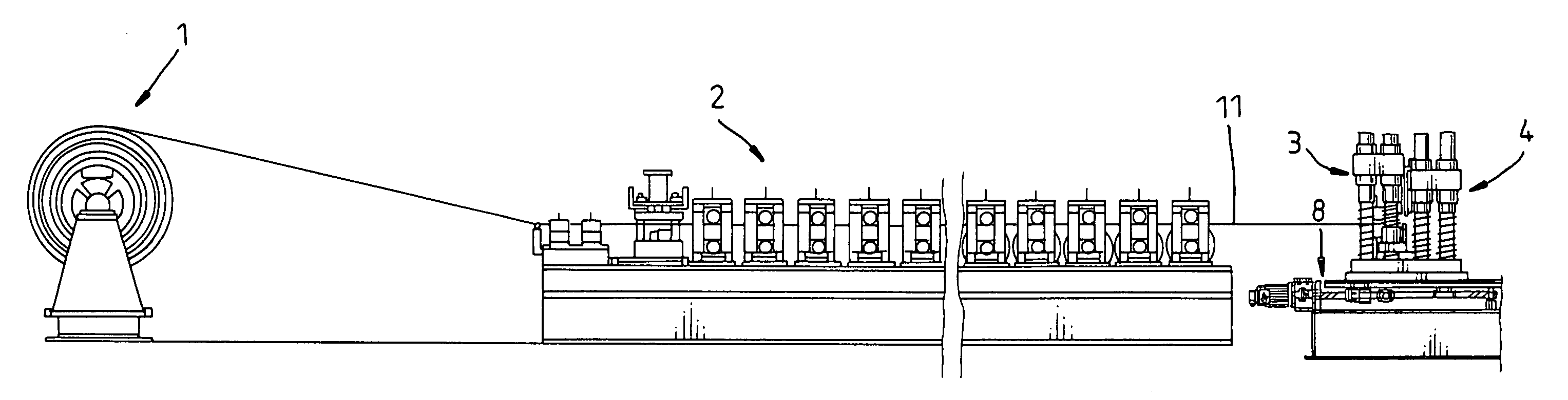
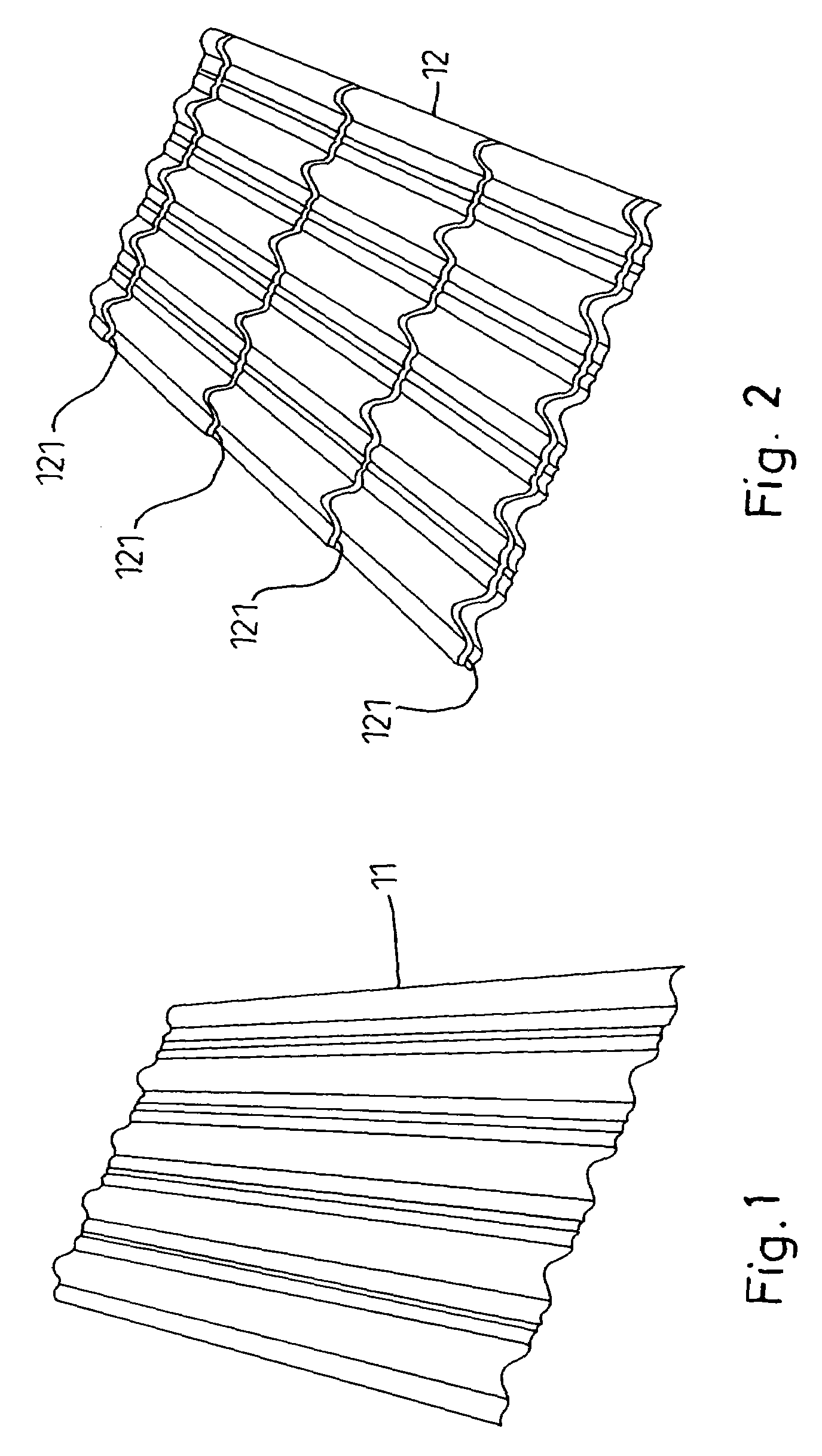
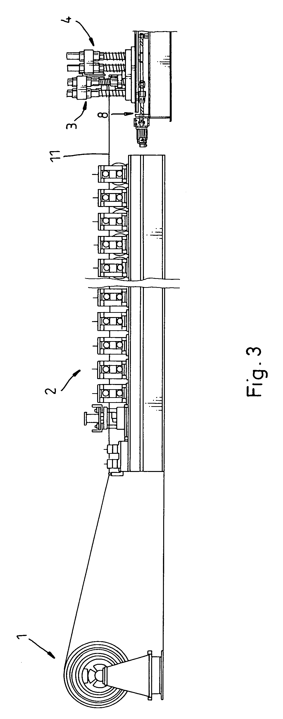
[0015]Referring to FIGS. 1–8, a metal encaustic tile making machine in accordance with the present invention comprises a corrugation forming roller unit 2 (see FIG. 3), which is controlled to corrugate a continuous sheet of metal sheet material 1 into a corrugated metal sheet 11 (see FIG. 1), an angle forming unit 3, which comprises a first mold 31 and a second mold 32 (see FIG. 4) and controlled to stamp the corrugated metal sheet 11 into a metal encaustic tile 12 having angles 121 that are arranged in parallel and extend across the corrugations of the corrugated metal sheet 11 (see FIG. 2), and a cutting unit 4, which is controlled to cut the finished metal encaustic tile 12 from the continuous sheet of metal sheet material 1.

[0016]The main features of the present invention are outlined hereinafter. The metal encaustic tile making machine further comprises a machine base 9, and a slide 8 slidably carrying the angle forming unit 3 and the cutting unit 4 on the machine base 9. The s...


PUM

PropertyMeasurementUnit
Angleaaaaaaaaaa
Speedaaaaaaaaaa

Abstract

A metal encaustic tile making machine includes a machine base, a corrugation forming roller unit controlled to corrugate a continuous sheet of metal sheet material into a corrugated metal sheet, an angle forming unit controlled to stamp the corrugated metal sheet into a metal encaustic tile having angles, a cutting unit controlled to cut the finished metal encaustic tile from the continuous sheet of metal sheet material, a slide carrying the angle forming unit and the cutting unit on the machine base, and a motor controlled to move the slide forwards / backwards along two parallel guide rails at the machine base via a transmission screw to fit the delivering speed of the continuous sheet of metal sheet material.

Description

BACKGROUND AND SUMMARY OF THE INVENTION[0001]The present invention relates to a machine for making tiles and more particularly, to a metal encaustic tile making machine, which uses a slide to carry an angle forming unit and a cutting unit on the machine base such that delivery of continuous sheet of metal sheet material keeps running during working of the angle forming unit and the cutting unit.[0002]In a conventional metal encaustic tile making machine, a continuous sheet of metal sheet material is delivered forwards at a constant speed to a corrugation forming roller unit for processing into a corrugated metal sheet. When operating the first mold and second mold of the angle forming unit of the encaustic tile making machine to make angles at the corrugated metal sheet, the feeding of the continuous sheet of metal sheet material must be stopped. This metal encaustic tile making procedure is complicated, resulting in low efficiency.[0003]The present invention has been accomplished u...

Claims


Application Information

Patent Timeline
IPC IPC(8): B21D13/10B23P23/00
CPCB21D13/10Y10T29/5116Y10T29/5136Y10T29/5142Y10T29/5124
Inventor CHUANG, SEN-JUNG
Owner CHUANG SEN JUNG
Why Eureka
Try Eureka