Apparatus for processing permeable or semi-permeable webs

a technology of permeable or semi-permeable webs and air processing equipment, which is applied in the direction of press section, lighting and heating equipment, drying machines with progressive movements, etc., can solve the problems of difficult to achieve the incorporation of multiple vacuum means within the roll so as to create different air flow zones on the drying cylinder, and limit the flow of the patent system. , to achieve the effect of easy transfer

Inactive Publication Date: 2006-05-09
VALMET OY
View PDF11 Cites 23 Cited by
  • Summary
  • Abstract
  • Description
  • Claims
  • Application Information

AI Technical Summary

Benefits of technology

[0012]Air is exhausted from the roll through the outer surface of the shell, a feature which makes it possible to enhance and control air flow by varying the shell length, something that is not possible with rolls that exhaust air through their axial ends only.
[0015]The present invention overcomes this drawback in energy consumption and achieves significant economies by neither limiting nor directing the air exhaust exclusively to the cylinder's roll ends. Instead, the exhaust air is impelled and directed through the shell of the cylinder, and the exhaust area can be expanded for any roll size merely by extending the width of the roll so as to keep exhaust velocities low and minimize energy consumption.
[0016]Since air is forced out of the cylinder surface, the area available for exhausting air is virtually unlimited and it can be increased by merely increasing the length of the cylinder. This exhaustability has significant process advantages over devices which employ cylinders whose exhaust area is confined to the cylinders axial ends.
[0017]Accordingly, the structure of the present roll makes it useful in high-flow applications because the exhaust air flow area can be increased by simply extending the outside length of the shell to any desired degree.
[0022]These channels limit the air flow to the radial and axial directions only and, thus, make it possible to divide the roll into numerous circumferential zones which may be processed independently.
[0024]This ability to divide the roll both circumferentially and axially makes it possible to achieve a checkerboard of processing zones so that several operations can be independently achieved on the same roll.

Problems solved by technology

Unfortunately however, this patented system is flow limited due to the vacuum source and, also, it is limited because air flow through the conduits is not distributed evenly.
Moreover, the incorporation of multiple vacuum means within the roll so as to create different zones of air flow on the drying cylinder is difficult to achieve because of the limited space within the cylinder.

Method used


Image

  • Apparatus for processing permeable or semi-permeable webs
  • Apparatus for processing permeable or semi-permeable webs
  • Apparatus for processing permeable or semi-permeable webs

Examples


Embodiment Construction

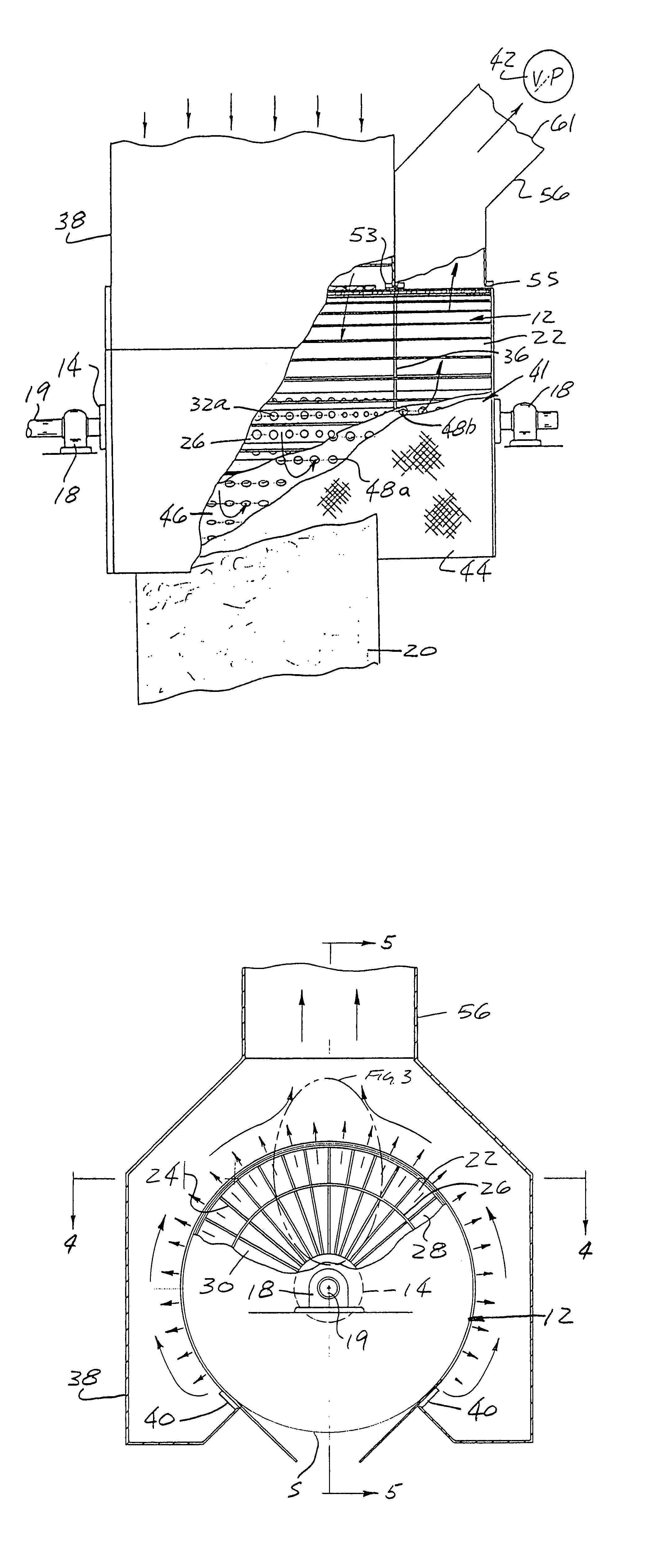
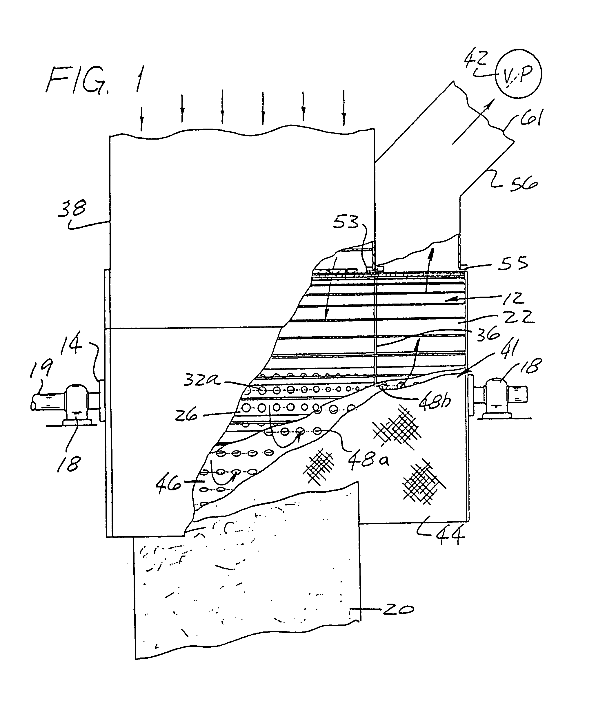
[0032]The use of this apparatus in drying permeable and semi-permeable webs is best illustrated by FIG. 1 which shows a web 20 being fed onto the drying cylinder of this invention by conventional guideroll means (not shown).

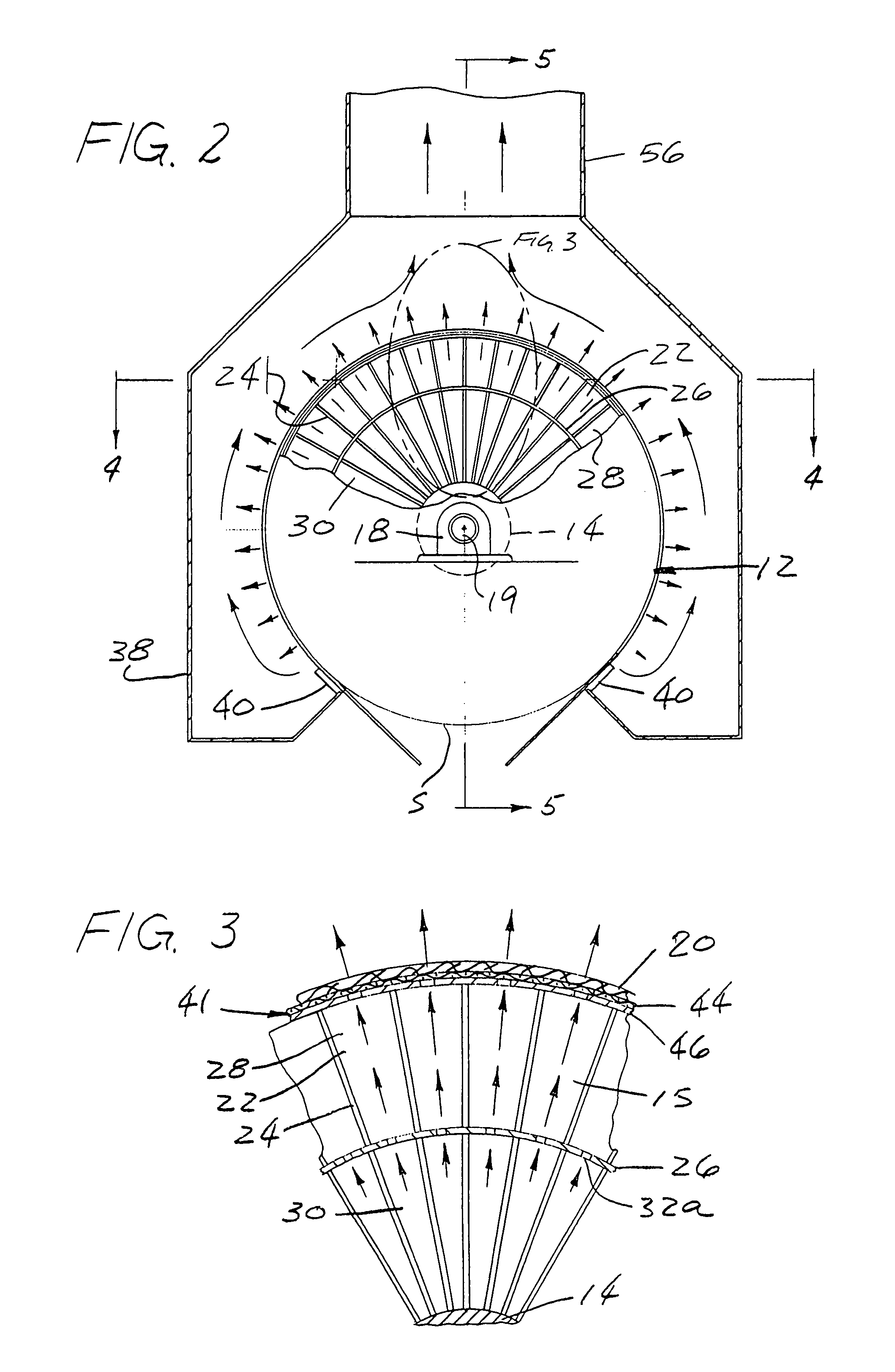
[0033]The drying cylinder 12 (FIGS. 1 and 2) consists essentially of a cylindrical hub 14 mounted on an axle 19 which is rotatably mounted in a pair of bearings 18. The cylinder 12 includes a plurality of axially extending conduits 22 arranged together in cylindrical configuration. These conduits 22 are formed by a plurality of radial plates 24 (FIG. 2) extending along the longitudinal axis of the drying cylinder 12. Plates 24 extend outward radially from hub 14 to the periphery of cylinder 12. Each of the conduits 22 has their radial plates 24 converging toward each other so as to form a generally inwardly tapered channel 15 where they intersect the cylindrical hub 14 (FIG. 3).

[0034]The conduits 22 are covered by a cylindrical shell 41 (FIG. 3) comprised of a sc...


PUM


Abstract

An air processing cylinder useful in drying, curing, thermal bonding, cooling, and web transferring materials such as fabrics, papers, and the like. Air is exhausted out of the cylinder surface through a plurality of conduits equipped with distribution means for profiling the flow of air. The drying cylinder further includes a duct network on its outer shell for exhausting air out of one axial area only or, alternatively, the drying cylinder may contain multiple duct networks for exhausting air out of several axial areas, each having its own flow characteristics.

Description

BACKGROUND OF THE INVENTION[0001]This invention relates to an air processing apparatus for drying, curing, thermal bonding, cooling, and web transferring permeable or semi-permeable webs such as fabrics, paper, or the like.[0002]Typical of such an apparatus is the honeycomb system described in U.S. Pat. No. 4,542,596. In this system, a non-rotating structure within the roll provides multiple zones for web processing and a vacuum is applied to a plurality of honeycomb grilled conduits so that the web can be dried uniformly and without the ‘blind spots’ which characterize other devices. Unfortunately however, this patented system is flow limited due to the vacuum source and, also, it is limited because air flow through the conduits is not distributed evenly. Moreover, the incorporation of multiple vacuum means within the roll so as to create different zones of air flow on the drying cylinder is difficult to achieve because of the limited space within the cylinder.[0003]The present inv...

Claims


Application Information

Patent Timeline
Patent Type & Authority Patents(United States)
IPC IPC(8): D06F58/00D21F5/18F26B13/16
CPCF26B13/16D21F5/182
Inventor BEAUMONT, DONALD F.
Owner VALMET OY
Why Eureka
Try Eureka