Ambient thermal energy recovery system

a thermal energy recovery and ambient technology, applied in the direction of heat pumps, lighting and heating apparatus, heating types, etc., can solve the problems of inability to meet the needs of users, and failure of refrigerant systems, etc., to achieve the effect of dissipating hea

Inactive Publication Date: 2006-05-09
FLAMMANG KEVIN E
View PDF14 Cites 53 Cited by
  • Summary
  • Abstract
  • Description
  • Claims
  • Application Information

AI Technical Summary

Benefits of technology

[0017]In the method of thermal energy recovery, the refrigerant fluid absorbs thermal energy from the ambient air while passing through the evaporator plate assembly. The compressor compresses the refrigerant fluid to increase the temperature of the fluid, which is then passed through the heat exchan

Problems solved by technology

For example, heat pumps generally are nonfunctional below approximately 20° F., and thus are less practical in colder climates.
Such systems were impractical in climates having temperatures low enough to freeze the water.
However, these refrigerant systems were subject to failure due to excessive pressure created by rapid temperature increases in the panels when the

Method used


Image

  • Ambient thermal energy recovery system
  • Ambient thermal energy recovery system
  • Ambient thermal energy recovery system

Examples


Embodiment Construction

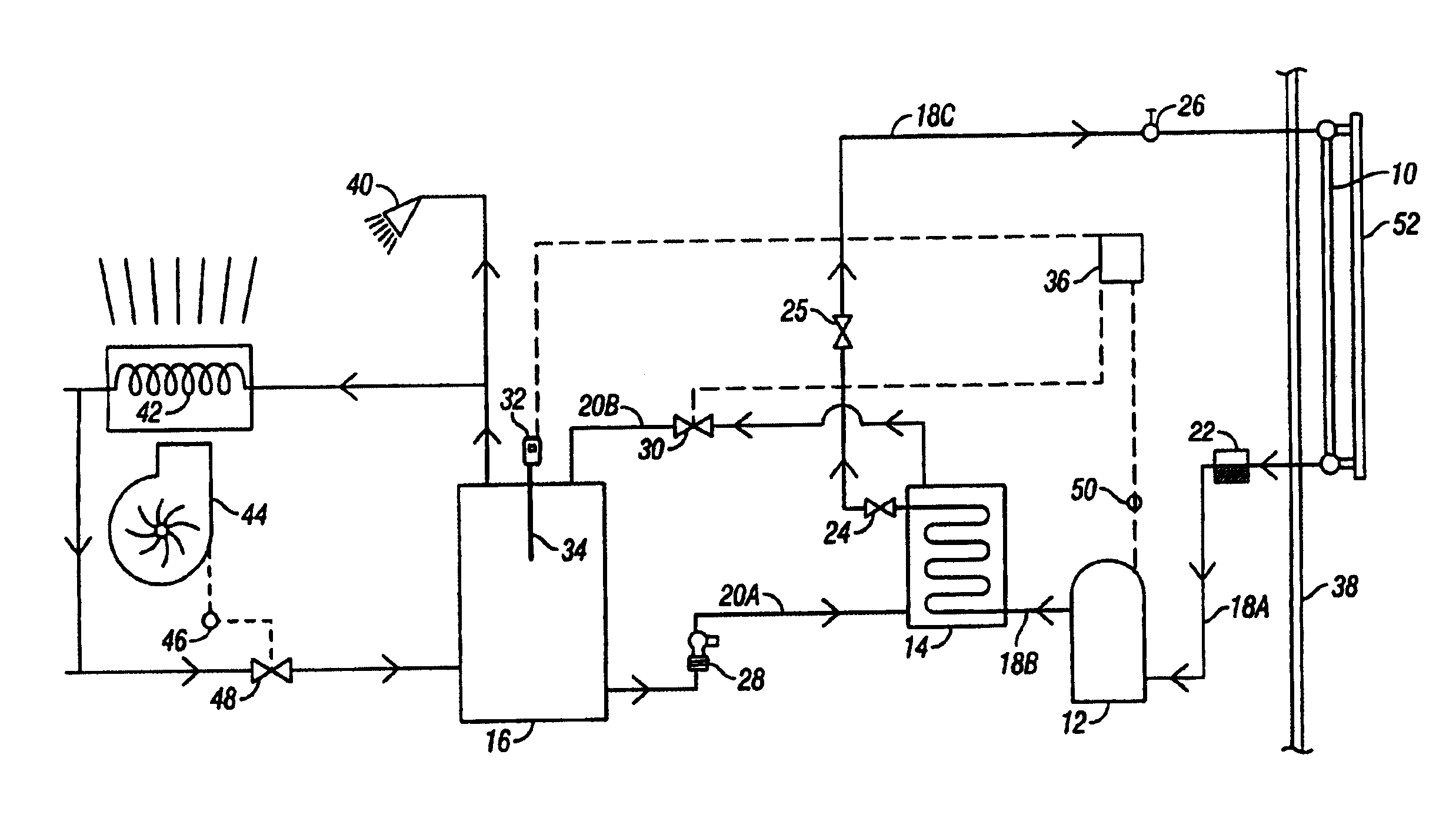
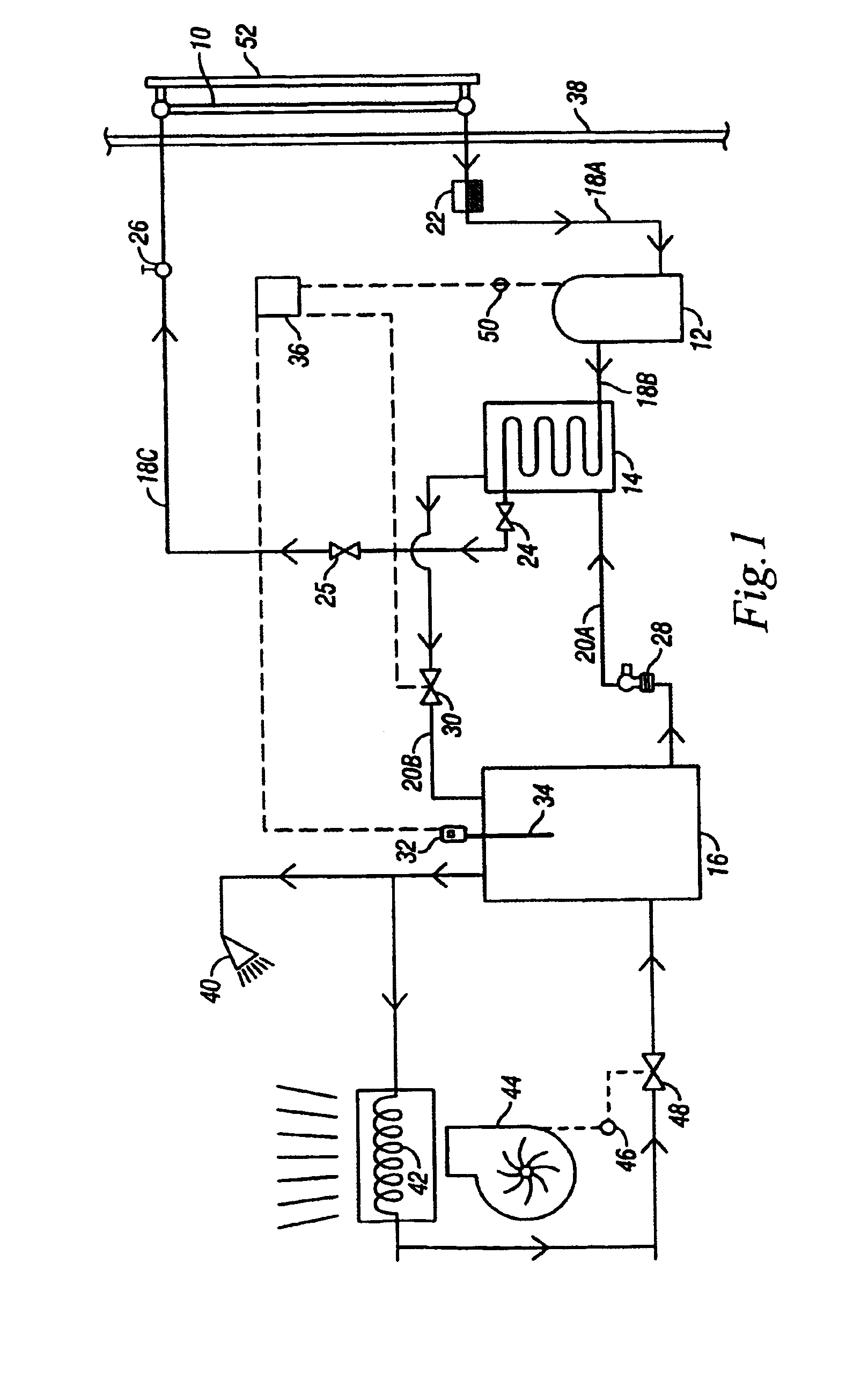
[0023]The basic components of the thermal energy recovery system of the present invention are an evaporator plate assembly 10, a compressor 12, a heat exchanger 14, and a hot water storage tank 16. Refrigerant fluid lines 18A, B, C provide a closed circuit loop between the evaporator plate assembly 10, the compressor 12, and the heat exchanger 14. The refrigerant fluid lines 18A, B, C are preferably made of hard copper, or similar material which will withstand rapid pressure increases. Soft copper, such as conventionally used in solar panels, will not suffice. Also, in the preferred embodiment, the fluid line 18A between the evaporator plate assembly 10 and the compressor 12 is ¾ inch diameter, while the line 18B between the compressor 12 and the heat exchanger 14 is ⅜ inch diameter. Thus, the fluid line 18A is low pressure, while the line 18B is high pressure. Water lines 20 provide a circuit between the heat exchanger 14 and the hot water storage tank 16. The size of the compresso...


PUM


Abstract

A method and system for recovering thermal energy from an ambient environment includes an evaporator plate assembly located in the ambient environment, such as outdoors to absorb thermal energy from air. A compressor, heat exchanger, and water storage tank are located indoors. Fluid lines provide a closed circuit between the evaporator plate assembly, the compressor, and the heat exchanger. Water lines provide a flow path between the exchanger and the hot water tank. Refrigerant fluid in the evaporator plate assembly absorbs thermal energy from the ambient environment, and the fluid is then compressed by the compressor to increase the temperature thereof. The heated fluid transfers thermal energy to water in the heat exchanger, which is then stored in the tank for use. The hot water can be circulated to furnace coils wherein air is blown over the coils to absorb heat therefrom, and used to heat one or more rooms.

Description

BACKGROUND OF THE INVENTION[0001]Heat pumps and solar panels are two types of thermal energy systems, both of which have shortcomings. For example, heat pumps generally are nonfunctional below approximately 20° F., and thus are less practical in colder climates. Solar panels are dependent upon the sun's rays, and therefore do not function at night or on cloudy days. The number of hours and days of sunlight in the particular geographic region are major factors in the usefulness of solar panels.[0002]Some prior art solar panels had water in the panel pipes and utilized large arrays to capture thermal energy from solar radiation for heating the water. A large surface area was required to adequately heat the water. Such systems were impractical in climates having temperatures low enough to freeze the water.[0003]Other prior art solar panel systems attempted to utilize refrigerant gasses in place of water in the solar panels. However, these refrigerant systems were subject to failure due...

Claims


Application Information

Patent Timeline
IPC IPC(8): F25B27/00
CPCF24D11/0214F25B30/02Y02B30/126F25B2339/047
Inventor FLAMMANG, KEVIN E.
Owner FLAMMANG KEVIN E
Why Eureka
Try Eureka