System and method for sheet transporting using dual capstan rollers

a technology of plate-type imaging and transporting media, which is applied in the field of transporting media in the imaging system of the plate-type printer, can solve problems such as inefficient use of media, and achieve the effects of reducing media tendency, minimizing or substantially eliminating imaging artifacts, and eliminating imaging artifacts

Inactive Publication Date: 2006-05-09
ECRM
View PDF37 Cites 4 Cited by
  • Summary
  • Abstract
  • Description
  • Claims
  • Application Information

AI Technical Summary

Benefits of technology

[0005]It is a feature and advantage of the present invention to provide a platesetter imaging system, having dual capstan rollers, that can record images over substantially the entire surface of a recording medium.
[0006]This and other objects of the present invention are realized in a system and method that, in at least one embodiment, feature two sets of capstan rollers, each having a driven roller and a non-driven roller, that translate media at a substantially same speed in forward and reverse directions through an imaging plane. As used herein, an imaging plane is where focused scanning laser light moves in a substantially straight line to create an image on the media. The capstan rollers have a substantially flat surface positioned between them to support the recording media. In at least one embodiment, the media is initially positioned using alignment pins to register the medium in a conventional manner known in the art. Subsequent to registration, the capstan. rollers engage the media, and the reference pins simultaneously or subsequently move down so that they do not obstruct the path of the media during imaging. Initially, the media is moved back (right-to-left when viewed from FIG. 1) so that the leading edge of the media is a sufficient distance from the second driven and non-driven roller to enable each of the first and second set of driven and non-driven rollers to accelerate to respective angular velocities that provide a substantially same speed at the periphery of the each of the first and second sets of driven and non-driven rollers. The angular velocities of, for example, the first and second driven (and non-driven) rollers may be slightly different due to differences in their respective diameters.
[0007]Subsequent to achieving positioning of the medium, the rollers are then preferably stopped. The rotational direction of the rollers is then reversed to start exposing, optionally from substantially up to and including the leading (i.e., the edge closest to the reference pins) and / or trailing edge (i.e., the edge farthest from the reference pins) of the medium.
[0008]In at least one embodiment, the first non-driven roller has a first horizontal offset from the first driven roller, and the second non-driven roller has a second horizontal offset from the second driven roller. We have discovered that these offsets advantageously prevent or reduce the tendency of the media from “wrapping around” the driven rollers, thereby minimizing or substantially eliminating imaging artifacts. The first horizontal offset is in a direction in which the medium exits from the platesetter and is approximately ten thousandths of an inch (0.010 inch). The second horizontal offset is in a direction in which the medium is received in the platesetter, and also is approximately ten thousandths of an inch (0.010 inch). We have also discovered that use of a plurality of independent shafts for each roller or group thereof also provides a substantially uniform force applied to the medium. This ensures that the medium is moved in a substantially straight direction.
[0009]In at least one embodiment, a separate motor is provided for each of the two driven rollers. A controller, for example, receives as input the speed at a periphery of each of the driven rollers, and controls the motors to provide a substantially same speed at the periphery of each driven roller taking into account, for example, a small variation or difference in diameter of the two driven rollers. This advantageously ensures that the medium is transported at a constant speed through the two sets of rollers, thereby minimizing and preferably eliminating imaging artifacts that may be caused by differences in speed at the periphery of each driven roller. In at least one embodiment, the controller can utilize different gains, a function of at least velocity of the medium, to minimize system disturbances and / or imaging artifacts from the medium coming into contact with the second set of rollers during imaging.
[0010]Using two sets of rollers, the system and method in accordance with the present invention can optionally and advantageously image onto media substantially from end-to-end, leaving no area of the media unexposed. In addition, the system and method in accordance with the present invention advantageously saves time by, for example, loading, imaging, and unloading media in a single low cost, full image operation. Finally, the dual capstan imaging system in accordance with the present invention enables imaging to be done in a manner that does not adversely affect the image being laid down on the medium.

Problems solved by technology

This results in inefficient use of media, and use of a media size that is necessarily larger than an image formed thereon.

Method used


Image

  • System and method for sheet transporting using dual capstan rollers
  • System and method for sheet transporting using dual capstan rollers
  • System and method for sheet transporting using dual capstan rollers

Examples


Embodiment Construction

including the description of a preferred structure as embodying features of the invention will be best understood when read in reference to the accompanying figures wherein:

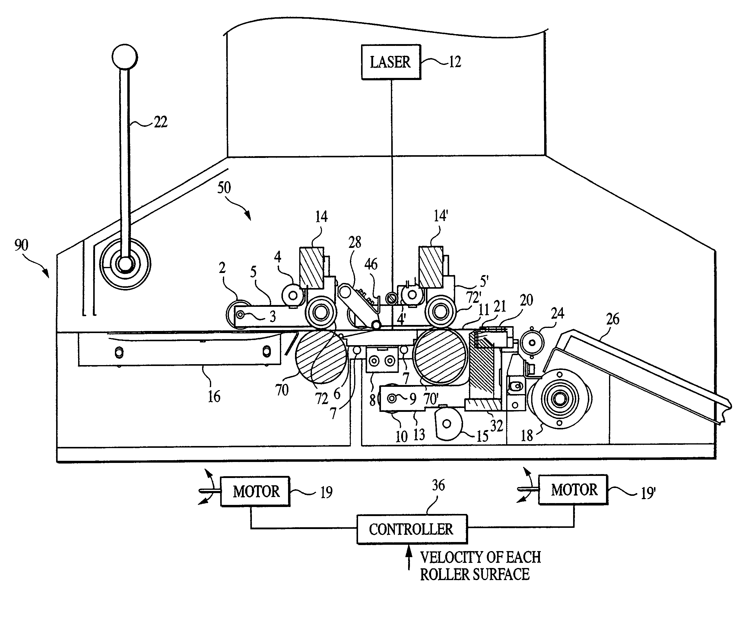
[0013]FIG. 1 is an elevation view of an exemplary platesetter imaging system embodying the present invention;

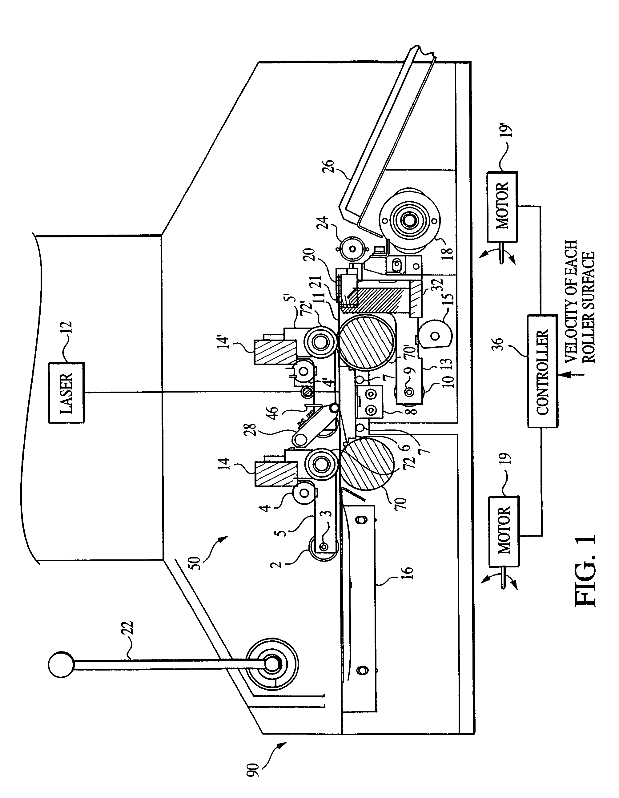
[0014]FIG. 2 is an exemplary perspective view of the upper and lower roller arrangement of the platesetter imaging system of FIG. 1;

[0015]FIG. 3A is an exemplary perspective view of the upper roller arrangement of the platesetter imaging system, showing additional details regarding roller arrangement;

[0016]FIG. 3B is an exemplary perspective view of the upper roller arrangement of the platesetter imaging system, showing the use of springs in keeping the rollers in contact with the medium;

[0017]FIG. 4 is an exemplary perspective view illustrating the alignment pins shown in FIG. 1;

[0018]FIG. 5 is an exemplary diagram showing the sequence of operation in transporting a recording medium during an imaging oper...


PUM


Abstract

A platesetting system and method comprising a pair of dual capstan rollers that receives a recording medium and records an image on the received medium as the medium is transported through the system. The system and method advantageously enable at least a portion of the image to extend from a leading edge of the medium to a trailing edge of the medium.

Description

CROSS-REFERENCE TO RELATED APPLICATION[0001]This application is a continuation of U.S. patent application Ser. No. 10 / 117,337, filed Apr. 8, 2002, which is hereby incorporated by reference herein in its entirety.BACKGROUND OF THE INVENTION[0002]The present invention relates generally to transporting media and, more particularly, to transporting media in a platesetter imaging system.[0003]In platesetting imaging systems in which media (e.g., metal and / or plastic sheet) are moved, conventional capstan drives cannot expose or form an image over an entire length of the media from end-to-end (i.e., from a leading edge of the media to a trailing edge of the media). This results in inefficient use of media, and use of a media size that is necessarily larger than an image formed thereon.[0004]There remains a need for a platesetter media transport and imaging system that provides end-to-end use of media, as well as a substantially consistent image quality throughout the entire image.SUMMARY ...

Claims


Application Information

Patent Timeline
Patent Type & Authority Patents(United States)
IPC IPC(8): B65H5/04B65H5/06B65H29/12
CPCB65H5/062B65H29/12Y10S271/902B65H2404/16B65H2701/1928B65H2404/143
Inventor ZEMBKO, MICHAEL C.BERRIGAN, JOHN W.CONNOLLY, JOHN L.
Owner ECRM
Why Eureka
Try Eureka