Clamping assembly

a technology of clamping sleeves and clamping rings, which is applied in the direction of couplings, machines/engines, manufacturing tools, etc., can solve the problems of increasing cutting and deformation effort, damage to the internal thread of the clamping sleeves, etc., and achieves the effect of facilitating the sliding on of the snap rings

Inactive Publication Date: 2006-05-09
ROBERT BOSCH GMBH
View PDF10 Cites 7 Cited by
  • Summary
  • Abstract
  • Description
  • Claims
  • Application Information

AI Technical Summary

Benefits of technology

[0004]In an example clamping assembly of the present invention, the clamping sleeve may be slid, from the end of the second component that faces out toward the support surface of the first component, onto the outer jacket of the second component. Due to the feature that the snap ring may be configured as a detent which elastically deflects in the radial direction, and that the second component has an undercut into which the snap ring may deform, and that an annular groove accommodating the snap ring may be formed on the inner wall of the clamping sleeve as an opposing detent, the clamping sleeve, when it is slid on, may be slid a bit past the snap ring, until the snap ring, which is elastically pretensioned as a result, snaps into the annular groove of the clamping sleeve, thereby captively mounting the clamping sleeve on the second component. When the clamping sleeve is subsequently screwed together with the first component, the snap ring is drawn out from the undercut and pressed against the clamping shoulder of the second component. A feature of this is that the threaded section of the clamping sleeve may not have to be pushed over the snap ring. By using the clamping assembly of the present invention, a robust attachment of the two components may be achieved, requiring little assembly effort and also, in particular, little structural space. The components may be joined only after complete machining, so that no captive parts have to be handled during the production process.
[0006]The inner wall of the clamping sleeve may have, at its end that is pressed onto the second component, a peripheral chamfer that facilitates the sliding on of the snap ring. When the clamping sleeve is slid on, the chamfer of the clamping sleeve may cooperate with the stop face of the second component in such a manner that the snap ring is deformed so as to slide radially inwardly into the undercut all along the chamfer without the aid of any tools.

Problems solved by technology

Moreover, these conditions may require increased cutting and deformation effort in the production of the second component.
For example, if, in addition, the first component should have an external thread and the clamping sleeve an internal thread that is screwed together with the external thread of the first component, the section of the clamping sleeve provided with the internal thread may be required to be slid over the outer jacket of the second component, which, on the one hand, may require a great amount of play between the internal thread of the clamping sleeve and the outer jacket and, on the other hand, may result in the internal thread of the clamping sleeve being damaged, for example, by pushing against the snap ring.

Method used


Image

  • Clamping assembly
  • Clamping assembly
  • Clamping assembly

Examples


Embodiment Construction

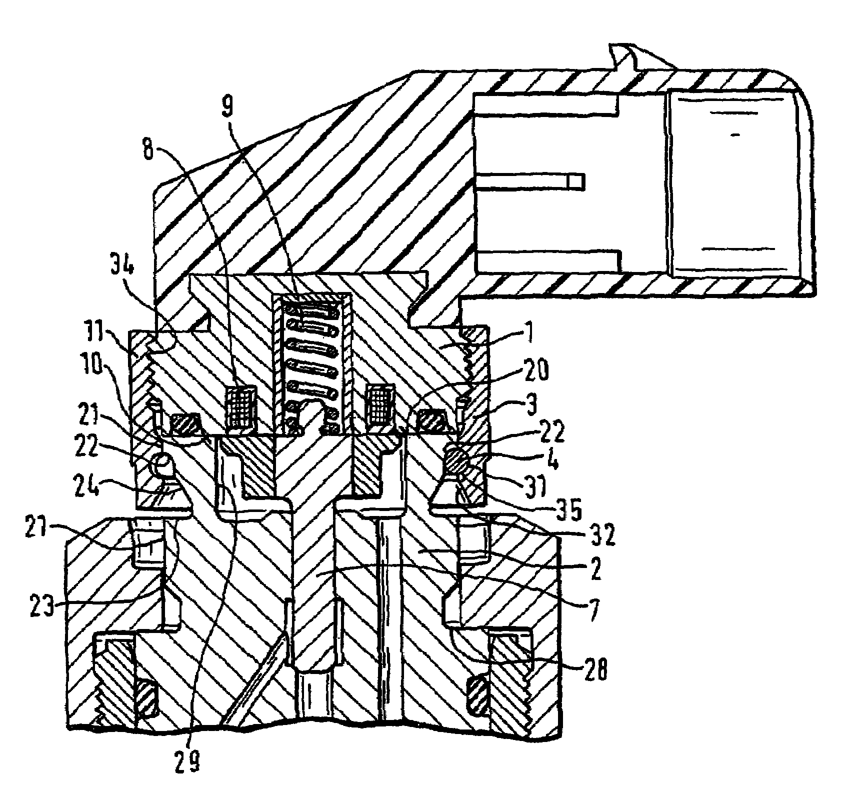
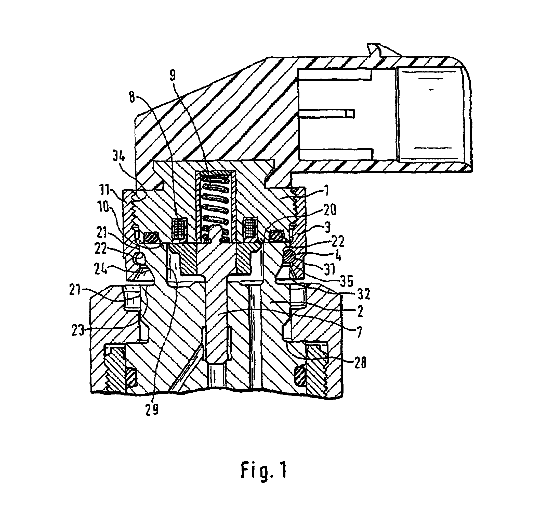
[0011]FIG. 1 shows a first example embodiment of a clamping assembly of the present invention. In this example embodiment, the clamping assembly is mounted on a fuel injector for internal combustion engines, a first component 1 of the clamping assembly being formed by the magnet assembly of the fuel injector. Magnet assembly 1 includes a magnetic core having pole face 10 and coil 8, as well as a valve spring 9, which impinges an axially movable armature 7 having a tie plate and tie bolt. A valve assembly of the fuel injector represents a second component 2 of the clamping assembly. Valve assembly 2 has a support surface 20 supported against pole face 10 of magnet assembly 1. A recess 29 in support surface 20 forms an armature compartment to accommodate armature 7. The movable armature controls the discharge of fuel from its control pressure chamber, which in turn controls the injection operation of the fuel injector. As illustrated in FIG. 1, the clamping assembly also includes a cl...


PUM


Abstract

A clamping assembly has a first component and a second component, which has an essentially cylindrical outer jacket, which is attachable to the first component. The clamping assembly has a support surface supported against the first component, which is able to be clamped against the first component via a clamping sleeve that is slid onto the outer jacket and may be screwed onto the first component, and via a snap ring that comes to rest against a first clamping shoulder formed on the inner wall of the clamping sleeve and against a second clamping shoulder formed on the outer jacket of the second component. The snap ring is configured as a detent that deflects elastically in a radial direction and the outer jacket of the second component is provided with an undercut behind the second clamping shoulder, when viewed in the axial direction, into which the elastically deflecting snap ring is able to be deformed radially inwardly so that the clamping sleeve may be guided over the snap ring when slid onto the outer jacket of the second component and the snap ring is able to be brought into engagement in an annular groove on the inner wall that is configured as an opposing detent.

Description

FIELD OF THE INVENTION[0001]The invention relates to a clamping assembly, such as, for example, for use on a fuel injector.BACKGROUND INFORMATION[0002]A clamping assembly of this type is discussed, for example, in German Published Patent Application No. 2 303 506. The clamping assembly shown there includes, as a first component, a cylinder head of an internal combustion engine. A fuel injector, representing the second component and having an essentially cylindrically shaped outer cover, has a support surface that rests against the cylinder head in a recess of the same and is clamped in the cylinder head via a clamping sleeve that is configured as a hollow screw and via a snap ring that is set in an annular groove of the fuel injector, for which purpose the clamping sleeve has an external thread that may be screwed into an internal thread of the cylinder head. For this purpose, the clamping sleeve has a recess on its end facing the cylinder head that functions as a first clamping sho...

Claims


Application Information

Patent Timeline
Patent Type & Authority Patents(United States)
IPC IPC(8): F16L27/00F02M51/06F02M61/10F02M61/16F16L19/02F16L37/088
CPCF02M61/168F16L37/088F16L19/0231F02M2200/8076Y10T403/73Y10S285/921F16B2200/67
Inventor NIESLONY, MARKUS
Owner ROBERT BOSCH GMBH
Why Eureka
Try Eureka