
Flexible printed circuit board

Inactive Publication Date: 2006-05-09
S PRINTING SOLUTION CO LTD
View PDF2 Cites 2 Cited by
  • Summary
  • Abstract
  • Description
  • Claims
  • Application Information

AI Technical Summary

Benefits of technology

[0021]To solve the above and / or other problems, it is, therefore, an aspect of the present invention to provide a flexible printed circuit board capable of reducing inductance value among components constituting impedance formed on the substrate.

Problems solved by technology

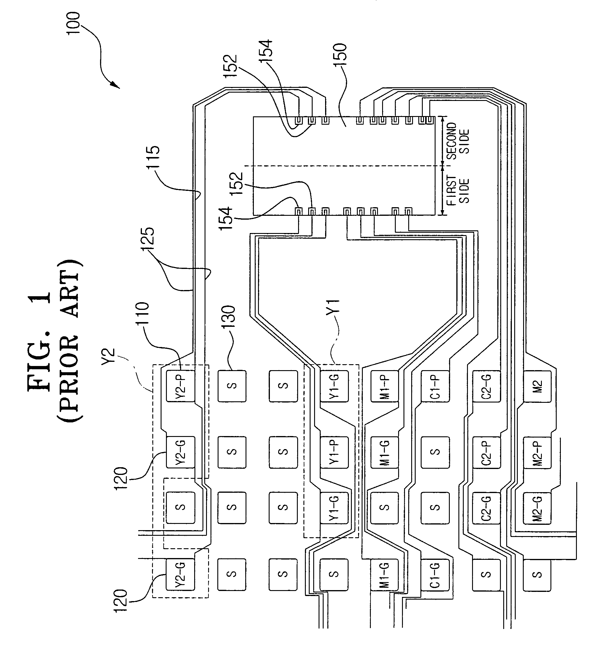
Accordingly, the FET element (not shown) for operating the printer head 150 cannot receive the necessary current amount, so that the heater (not shown) is not properly heated and printing speed may not be increased, or may be delayed.

Method used


Image

  • Flexible printed circuit board
  • Flexible printed circuit board
  • Flexible printed circuit board

Examples


Embodiment Construction

[0033]Reference will now be made in detail to the embodiments of the present invention, examples of which are illustrated in the accompanying drawings, wherein like reference numerals refer to the like elements throughout. The embodiments are described below to explain the present invention by referring to the figures.

[0034]The matters defined in the description, such as the detailed construction and elements, are only provided to assist in a comprehensive understanding of the invention. Thus, it is apparent that the present invention can be carried out without those defined matters. Also, well-known functions or constructions are not described in detail, since they would obscure the invention in unnecessary detail.

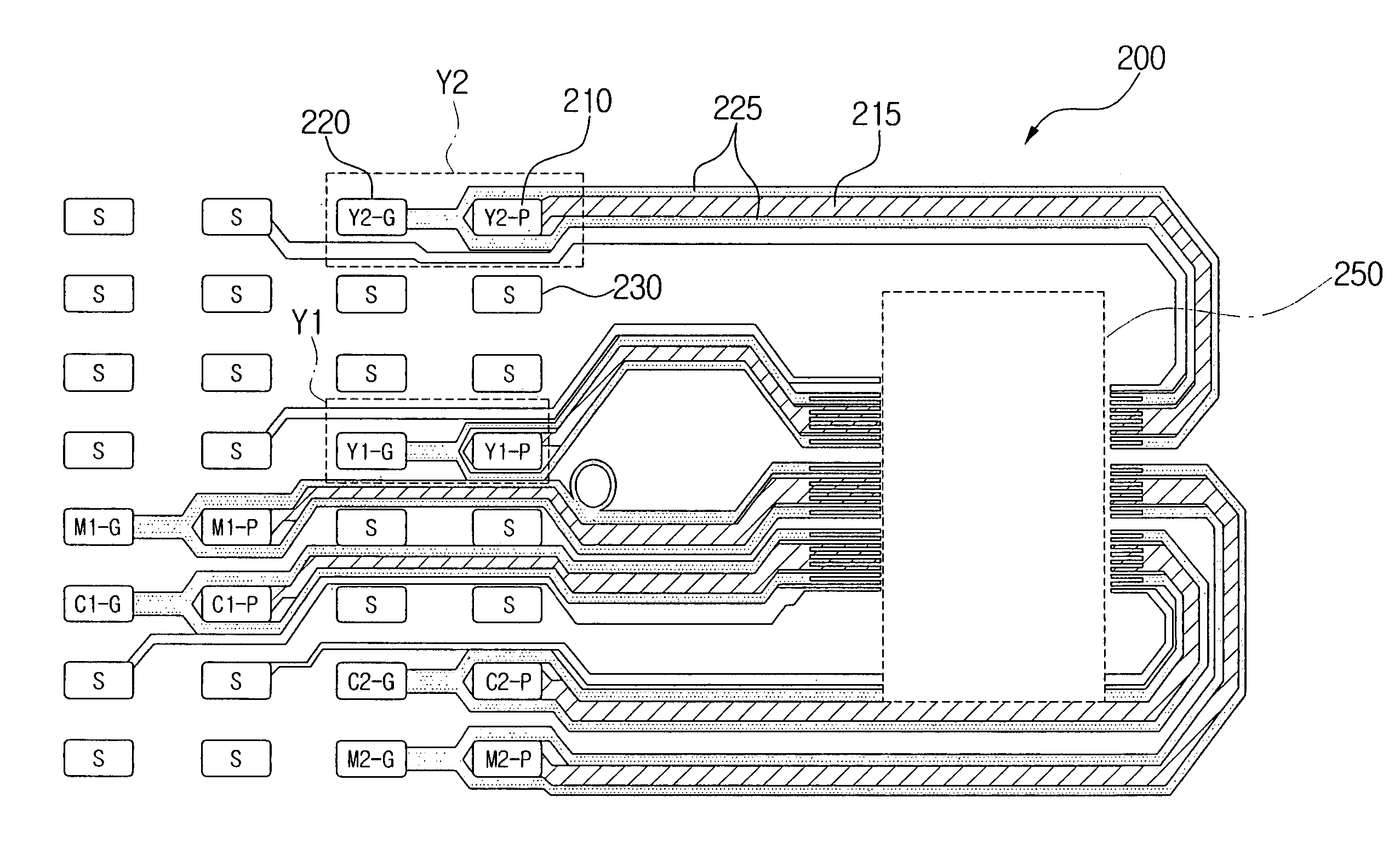
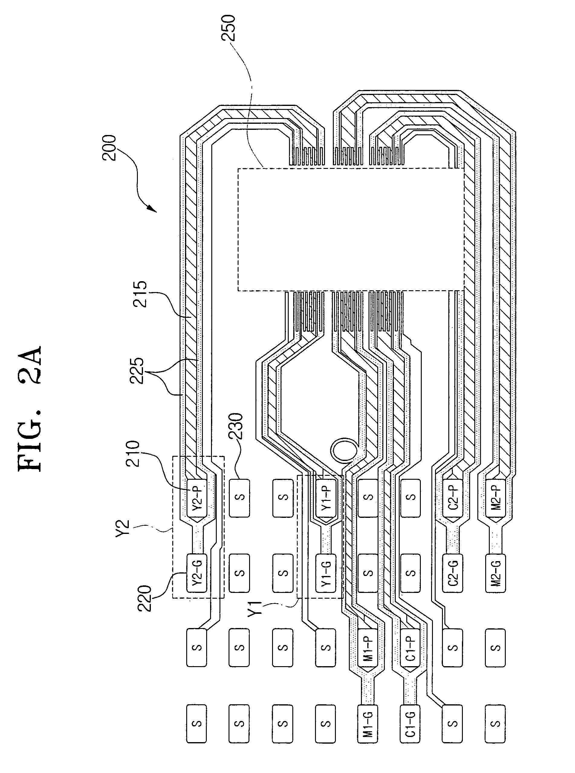
[0035]FIG. 2A is a schematic plan view of a part of a flexible printed circuit board connected to a printer head according to an embodiment of the present invention, and FIG. 2B is a drawing schematically showing the printer head connected to the flexible printed circuit ...


PUM


Abstract

A flexible printed circuit board connected to a printer head having at least one heater discharging ink, the flexible printed circuit board including: at least one voltage supplying terminal selectively supplying an operating voltage to the at least one heater in response to receiving a printing command signal from a printer; at least one first cable connected at each end to the at least one voltage supplying terminal and at least one first bonding pad, respectively, transferring the operating voltage to the at least one heater; at least one grounded terminal; and at least one second cable connected at each end to the at least one grounded terminal and at least one second bonding pad, respectively, in which the at least one second cable is divided into at least two portions at a predetermined position and a first portion of the at least two divided portions is provided along one side of the at least one first cable, and a second portion of the at least two divided portions is provided along the other side of the first cable.

Description

CROSS-REFERENCE TO RELATED APPLICATIONS[0001]This application claims the benefit of Korean Application No. 2002-70908, filed Nov. 14, 2002, in the Korean Intellectual Property Office, the disclosure of which is incorporated herein by reference.BACKGROUND OF THE INVENTION[0002]1. Field of the Invention[0003]The present invention relates to a flexible printed circuit board, and, more particularly, to a flexible printed circuit board connected to a printer head, which provides improvement in printing speed through impedance reduction.[0004]2. Description of the Related Art[0005]In general, printing machines, such as an inkjet printer or a duplicating machine, form an image using an ink cartridge. The ink cartridge emits, to a printing paper, a monochromatic or color ink stored in the ink cartridge through a printer head according to a printing command signal, i.e., according to a heater selection signal provided from the printing machine. The printer head is a substrate for firing ink,...

Claims


Application Information

Patent Timeline
IPC IPC(8): B41J2/05B41J2/14B41J2/07B41J2/175H05K1/02H05K1/11
CPCB41J2/14072B41J2/1753H05K1/0219H05K2201/09236H05K1/118B41J2/07
Inventor KIM, JEONG-SEONJUNG, MYUNG-SONGLEE, JAE-CHEALCHO, SEO-HYUN
Owner S PRINTING SOLUTION CO LTD
Learn More