
Device and process for the production and transfer of heating and cooling power

Inactive Publication Date: 2017-05-25
COLOGNESI ERNESTO
View PDF8 Cites 2 Cited by
  • Summary
  • Abstract
  • Description
  • Claims
  • Application Information

AI Technical Summary

Benefits of technology

The invention is a device that can use electrocaloric materials to produce heat or cooling with minimal power consumption. It does not require a separate power source and can transfer energy to a second inductor without adding any further power. The device also includes a pulse source with a predetermined duty cycle, such as a gallium nitride field-effect transistor, to further improve its performance and reduce losses. Overall, the device has reduced power consumption and improved efficiency.

Problems solved by technology

In fact, in the traditional art the active power, i.e. the same type of electric power which can activate electric motors, turn on lights or other types of heating or cooling utilities, is believed to be the only one usable, whereas the reactive power would not be usable and would only burden the power-distribution networks and the plants connected thereto.

Method used


Image

  • Device and process for the production and transfer of heating and cooling power
  • Device and process for the production and transfer of heating and cooling power
  • Device and process for the production and transfer of heating and cooling power

Examples


example 1

Implementation of a Prototype of Heating Element

[0078]A prototype of flat capacitor having the dielectric made up of two layers close to each other and adhering to the plates has been implemented. The first dielectric was a terpolymer PVDF-TrFE-CTFE (elettrocaloric material), whereas the second layer was constituted by air. Thus, the equivalent diagram is that of two capacitors connected in series, as depicted in FIG. 13.

[0079]The characteristics of the dielectric terpolymer were as follows:[0080]Side=0.03×0.03 m[0081]Surface S=0.0009 m2 [0082]Thickness of the PVDF-TrFE-CTFE film=10 μm

[0083]Taking into account the dielectric constant in the vacuum (ε0=8.854*10−12 F / m), the values of the capacitances C1 (terpolymer) and C2 (air) were calculated.

[0084]The value of C1 was calculated as follows:

[0085]Relative permittivity of the terpolymer εr1=37

ε1=327.6*10−12 F / m=εr1×ε0

C1=29.480*10−12 F (ε1*Surface / Thickness)

[0086]The value of C2 was in turn calculated as follows:[0087]Air thickness=4...

example 2

Experimental Tests

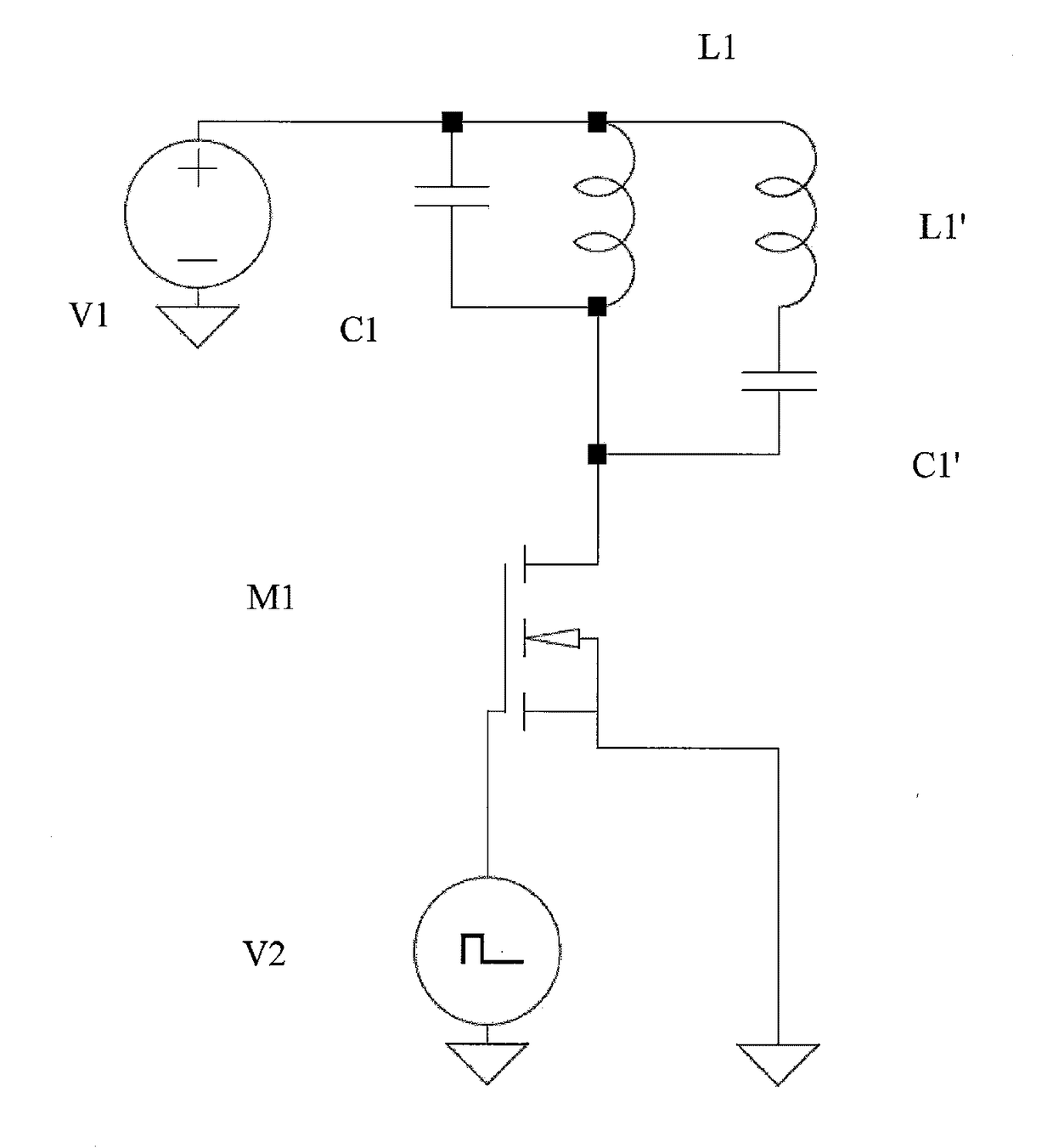
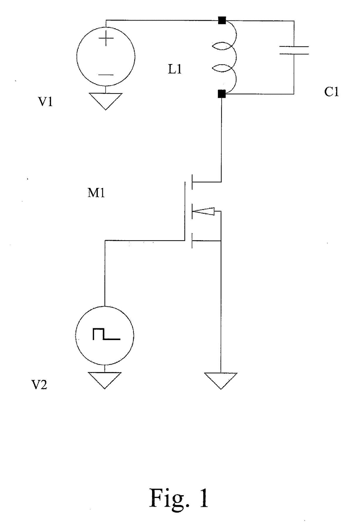
[0090]The capacitor made according to the example has been connected in parallel to an inductor, as in the circuit of FIG. 1.

[0091]A sinusoidal voltage with a working frequency of 87,600 Hz (87.6 kHz) and effective value of the voltage of 200 Vrms was selected to be set in the circuit.

[0092]Once the total capacitance of the capacitor is known, the inductance value that satisfies the relation with the working frequency of 87.6 kHz was calculated to be 1.86 mH.

[0093]The heat generated by the PVDF-TrFE-CTFE film was compared with the heat generated by an electrical resistance of 220Ω powered at 22.69 volts and a current absorption of 0.103136 A.

[0094]As the temperature of the two systems reached 50° C., it was possible to calculate the thermal power generated by the elettrocaloric film by detecting the electric power consumed by the resistor, equal to 2.34 W.

[0095]The power shares absorbed by each part of the capacitor prototype of Example 1 were calculated by taking ...


PUM


Abstract

A device and process for the production and transfer of heating and cooling power are described, in which a resonant electric circuit having a capacitor with a dielectric of electrocaloric material connected to an inductor is used. The resonant circuit has comprises a variable electrical power supply section with a working frequency corresponding to the resonance frequency of the circuit.

Description

FIELD OF THE INVENTION[0001]The present invention relates a device and process for the production and transfer of heating and cooling power and, in particular, a device and process exploiting properties of electrocaloric dielectric materials in an electrical circuit suitably powered by an electrical power supply source.PRIOR ART[0002]Some types of materials show the electrocaloric effect in the form of temperature change of the material when an electric field is applied to the material itself; however, the effect is reversible, that is to say that in the absence of electric field, the material returns to its initial temperature. Generally, materials having this property are dielectric materials and can be used to make capacitors.[0003]Various materials having these properties have long been known and have been studied for several years, although no practical applications have been found. Only in more recent years, new polymers and ceramic materials have been studied, in the form of ...

Claims


Application Information

Patent Timeline
IPC IPC(8): F25B21/00
CPCF25B2321/001F25B21/00Y02B30/00H05B6/06H02J50/12H01G4/018H03H7/0115
Inventor COLOGNESI, ERNESTO
Owner COLOGNESI ERNESTO
Learn More