Illumination device and liquid crystal display device

a liquid crystal display and illumination device technology, applied in the direction of instruments, lighting and heating devices, mechanical devices, etc., can solve the problems of power consumption, limited number of light emitting elements, and it is substantially impossible for such a single-led front light to uniformly display, etc., to achieve high brightness uniformity, high display visibility, and high luminance

Inactive Publication Date: 2006-05-09
ALPS ALPINE CO LTD
View PDF12 Cites 29 Cited by
  • Summary
  • Abstract
  • Description
  • Claims
  • Application Information

AI Technical Summary

Benefits of technology

[0034]Since the liquid crystal display device includes the illumination device of the present invention, even when the single light emitting element is used in the illumin...

Problems solved by technology

That is, the number of light emitting elements is limited to reduce the power consumption.
It is, however, substantially impossible for such a single-LED front light to uniformly and brightly illuminate a large display region having a diagonal size of several inches or more by a combination of the thin light guide plate and the single light emitting element.
Consequently, the emitt...

Method used


Image

  • Illumination device and liquid crystal display device
  • Illumination device and liquid crystal display device
  • Illumination device and liquid crystal display device

Examples


first embodiment

[Overall Configuration of Liquid Crystal Display Device]

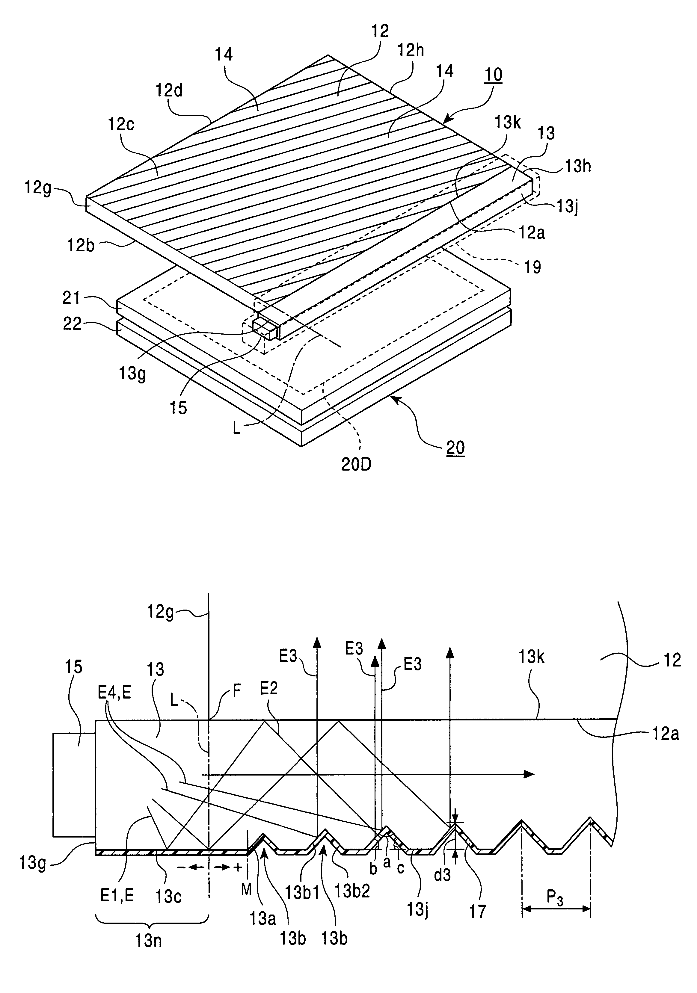
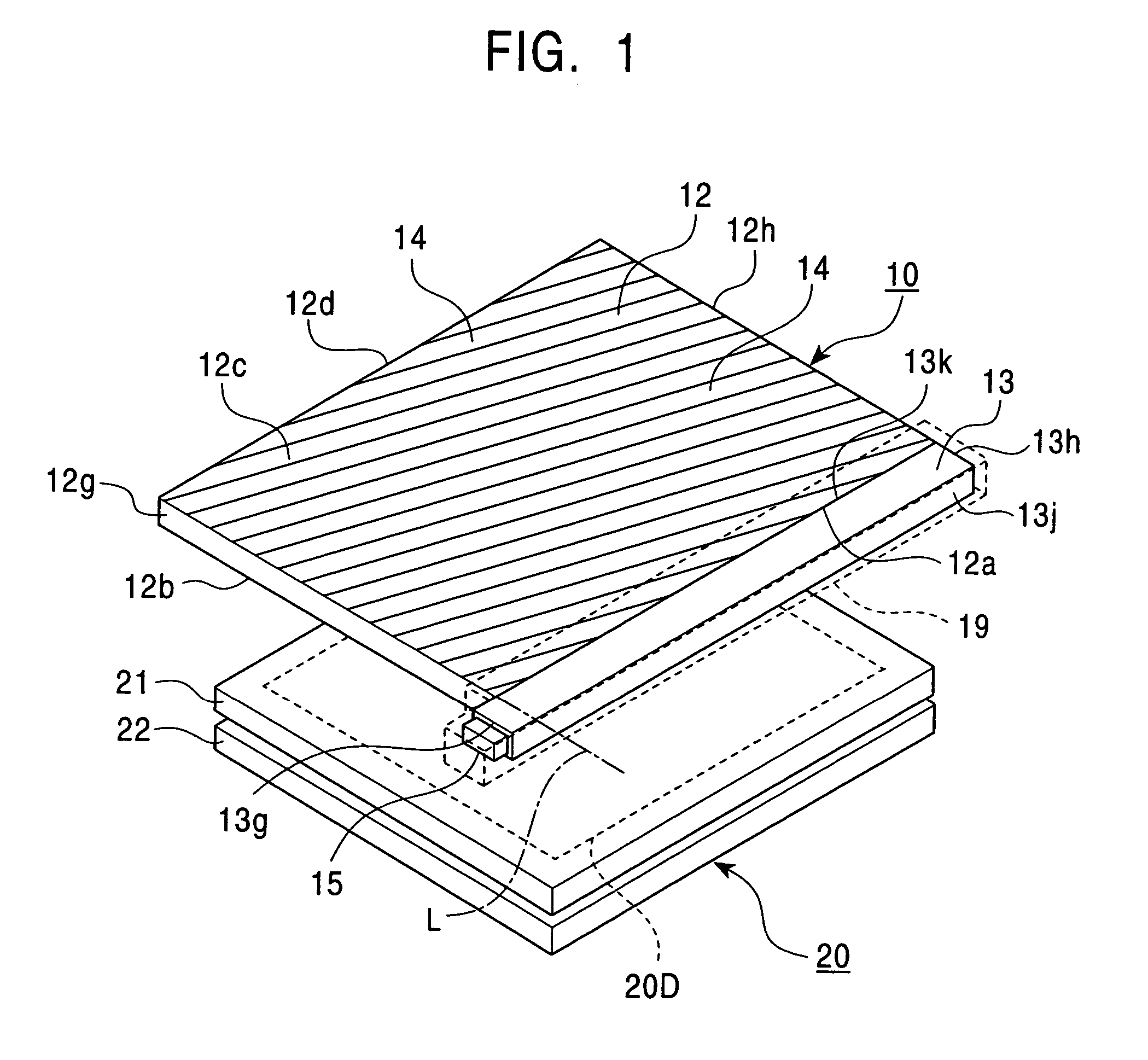
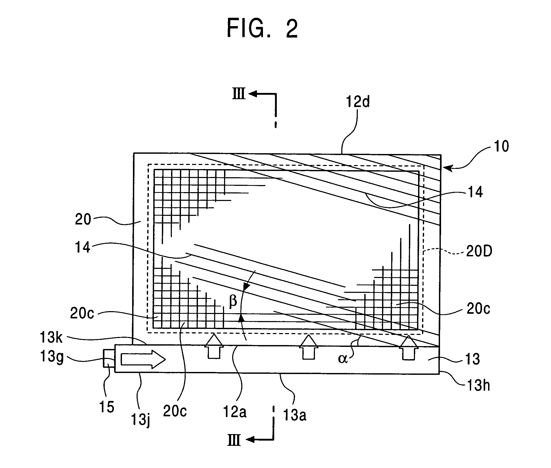
[0050]FIG. 1 is a perspective structural view of a liquid crystal display device according to a first embodiment of the present invention, FIG. 2 is a structural plan view of the liquid crystal display device shown in FIG. 1, and FIG. 3 is a cross-sectional view of the liquid crystal display device, taken along line III—III in FIG. 2. Referring to FIGS. 1 to 3, the liquid crystal display device of the first embodiment includes a front light (illumination device) 10, and a reflective liquid crystal display unit 20 disposed on the back side (lower side in the figures) of the front light 10.

[0051]As shown in FIG. 1, the front light 10 includes a substantially flat transparent light guide plate 12, an intermediate light guide 13 disposed along a side face (one side face) 12a of the light guide plate 12, a light emitting element 15 disposed at one end face 13g in the lengthwise direction of the intermediate light guide 13, and a cas...

second embodiment

[0099]A liquid crystal display device according to a second embodiment of the present invention will now be described with reference to FIG. 11. FIG. 11 is a perspective structural view of the liquid crystal display device of the second embodiment.

[0100]A front light 50 provided in the liquid crystal display device of the second embodiment is different from the front light 10 of in the first embodiment in that the extending direction of prism grooves 54 formed on a light guide plate 12 does not intersect a light incident face 12a, that is, in that the extending direction of the prism grooves 54 is parallel to the light incident face 12a. Since other structures are similar to those in the front light 10 shown in FIGS. 1 to 3, detailed descriptions thereof are omitted below. Since the basic configuration of a liquid crystal display unit 20 is equivalent to that in the liquid crystal display unit shown in FIGS. 1 to 3, a detailed description thereof is also omitted. In the liquid cryst...

third embodiment

[0102]A liquid crystal display device according to a third embodiment of the present invention will now be described. FIG. 12 is an enlarged structural plan view showing the principal part of a front light provided in the liquid crystal display device of the third embodiment.

[0103]A front light 60 provided in the liquid crystal display device of the third embodiment is different from the front light 10 of the first embodiment in that a prism face 13a is also formed on an outer side face 13j of a protruding portion 13n of an intermediate light guide 13, that is, in that the prism face 13a provided on the outer side face 13j of the intermediate light guide 13 close to a light emitting element 15 reaches an end face 13g of the intermediate light guide 13 close to the light emitting element 15 (in other words, the distance between the formation start position of the prism face 13a on the side of the light emitting element 15, and the end face 13g is substantially zero). Since other stru...


PUM


Abstract

In a front light, an intermediate light guide protrudes from a light guide plate toward a light emitting element in the direction along a light incident face of the light guide plate. A side face of the intermediate light guide opposing the light incident face serves as an emergent face from which light from the light emitting element is emitted to the light guide plate, and an outer side face remote from the emergent face serves as a reflecting face for reflecting light propagating inside the intermediate light guide. The outer side face of the intermediate light guide is provided with a prism face having a plurality of grooves of wedge-shaped cross section, and a reflective film formed thereon. The prism face is provided distant from an end face of the intermediate light guide close to the light emitting element.

Description

BACKGROUND OF THE INVENTION[0001]1. Field of the Invention[0002]The present invention relates to an illumination device and a liquid crystal display device, and more particularly, to the configuration of an illumination device that achieves a highly uniform distribution of the amount of emitted light with a single light source, and to the configuration of a liquid crystal display device using the illumination device.[0003]2. Description of the Related Art[0004]Front lights of reflective liquid crystal display devices have been formed in a unit including a light source, an intermediate light guide, a light guide plate, and a case member having a reflective inner surface to hold these members together.[0005]FIG. 13A is a perspective structural view of a conventional liquid crystal display device, and FIG. 13B is a plan view of a front light provided in the liquid crystal display device shown in FIG. 13A, as viewed from the viewing side. The liquid crystal display device shown in these...

Claims


Application Information

Patent Timeline
IPC IPC(8): F21V7/04F21V8/00G02B6/00F21Y101/02G02F1/1335G02F1/13357
CPCG02B6/0038G02F2001/133616G02F1/133616G02F1/1335
Inventor SUGIURA, TAKUROYAMASHITA, TATSUMARO
Owner ALPS ALPINE CO LTD
Why Eureka
Try Eureka