Device test apparatus and test method including control unit(s) between controller and test units

a test apparatus and device technology, applied in the direction of automated test systems, semiconductor/solid-state device testing/measurement, instruments, etc., can solve problems such as lowering testing efficiency, and achieve the effect of improving testing efficiency

Inactive Publication Date: 2006-05-09
SHARP KK
View PDF3 Cites 21 Cited by
  • Summary
  • Abstract
  • Description
  • Claims
  • Application Information

AI Technical Summary

Benefits of technology

[0011]The present invention has been made with the aim of solving the above problems, and it is an object of the present invention to provide a test apparatus and a test method capable of simultaneously performing independent tests on a large number of devices-under-test and significantly improving the testing efficiency.

Problems solved by technology

As a result, there is the problem of lowered testing efficiency which influences mass-production.

Method used


Image

  • Device test apparatus and test method including control unit(s) between controller and test units
  • Device test apparatus and test method including control unit(s) between controller and test units
  • Device test apparatus and test method including control unit(s) between controller and test units

Examples


Embodiment Construction

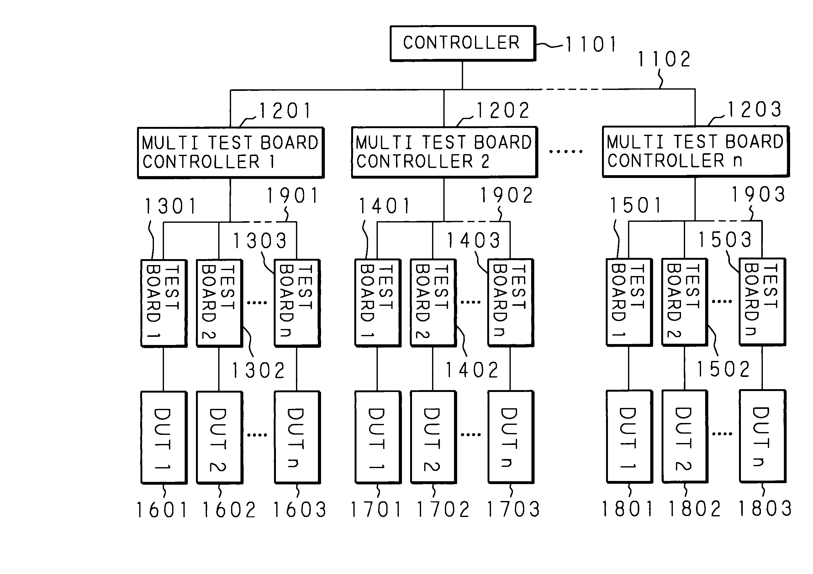
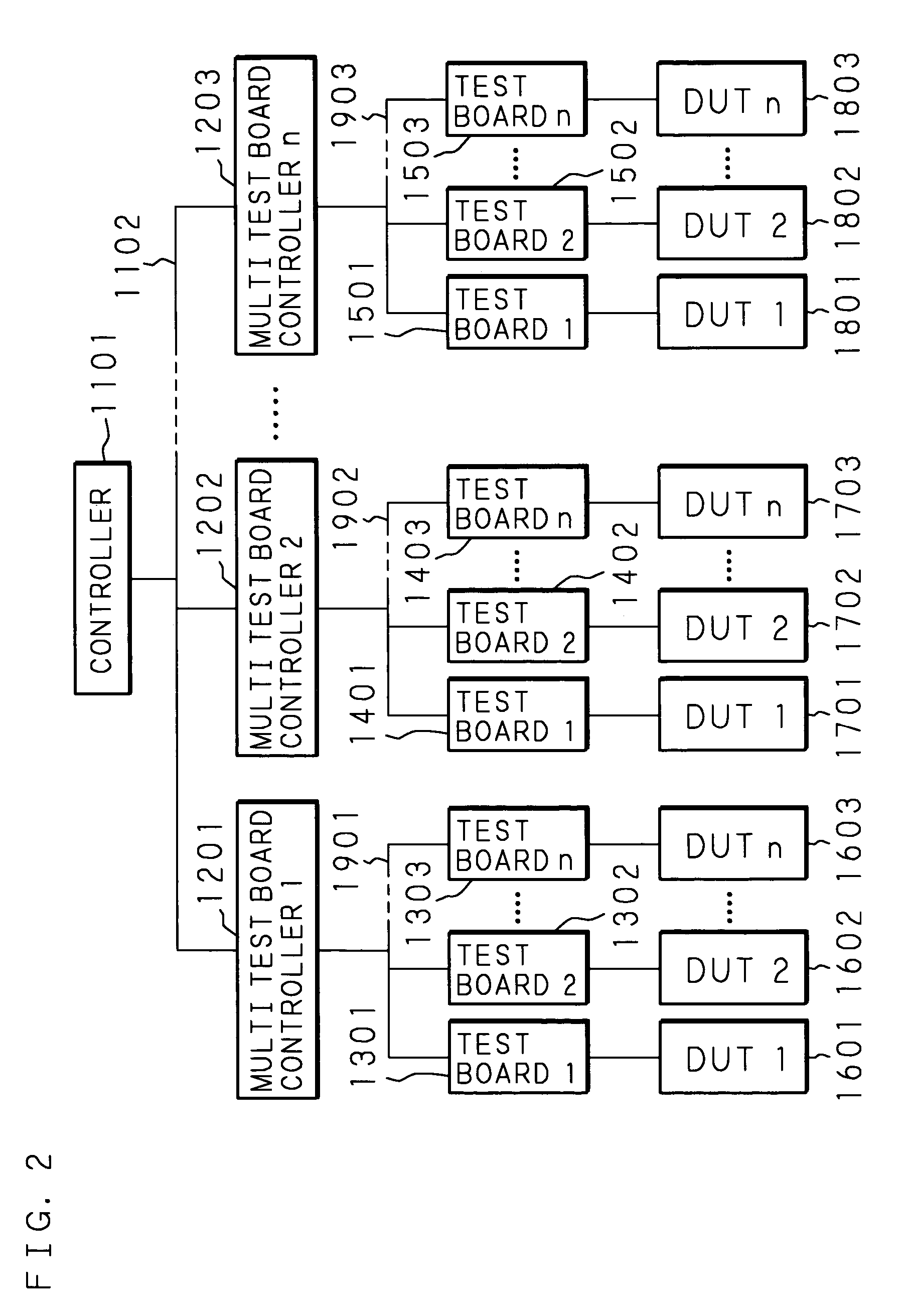
[0025]The following description will specifically explain the present invention with reference to the drawings illustrating an embodiment thereof. FIGS. 2 through 5B are views for explaining a test apparatus according to the present invention, and more specifically FIG. 2 is a view showing the entire structure of the present invention, FIG. 3 is a view showing the internal structure of the multi test board controller shown in FIG. 2, FIG. 4 is a view showing the internal structure of the test boards shown in FIG. 2, and FIGS. 5A and 5B are views showing the connection state of the multi test board controller and the test board.

[0026]As shown in FIG. 2, a test apparatus of the present invention for devices-under-test; such as semiconductor integrated circuits, comprises: one controller 1101; a plurality of multi test board controllers 1201–1203 as control units; and a plurality of test boards 1301–1303, 1401–1403, 1501–1503 connected as test units to the respective multi test board c...


PUM


Abstract

One test board for executing a test is provided for each of a plurality of DUTs (Devices-Under-Test) such as semiconductor integrated circuits, a multi test board controller for managing these test boards is provided, and a plurality of test boards managed by each multi test board controller are operated in parallel to simultaneously perform independent tests on the respective DUTs.

Description

CROSS-REFERENCE TO RELATED APPLICATION[0001]This non-provisional application claims priority under 35 U.S.C. §119(a) on Patent Application No. 2003-155827 filed in Japan on May 30, 2003, the entire contents of which are hereby incorporated by reference.BACKGROUND OF THE INVENTION[0002]The present invention relates to an apparatus and method for testing devices-under-test, for example, semiconductor integrated circuits such as an LSI wafer, and more particularly relates to a test apparatus and a test method capable of simultaneously performing independent tests on a large number of devices-under-test.[0003]Conventionally, independent tests are simultaneously carried out on a plurality of devices-under-test (for example, Japanese Utility Model Application Laid-Open No. 64-47148 / 1989). FIG. 1 is a block diagram of a conventional test apparatus disclosed in Japanese Utility Model Application Laid-Open No. 64-47148 / 1989. This test apparatus comprises: a plurality of test units 31–33 cont...

Claims


Application Information

Patent Timeline
Patent Type & Authority Patents(United States)
IPC IPC(8): G01R31/26G01R31/28G01R31/319H01L21/66
CPCG01R31/31926G01R31/2851G01R31/2834G07D2211/00G07F19/201
Inventor MATSUMOTO, KYOZO
Owner SHARP KK
Why Eureka
Try Eureka