Image signal output method, image signal output device, rangefinder, and imaging device

a technology of image signal and output method, which is applied in the direction of printers, distance measurement, camera focusing arrangement, etc., can solve the problems of deteriorating rangefinding accuracy, unable to make appropriate corrections for normal sensor arrays producing outputs whose difference increases with increasing incident light amount, and the difference between outputs increases with increasing amount. , to achieve the effect of improving rangefinding accuracy, enhancing imaging accuracy, and improving focusing accuracy

Inactive Publication Date: 2006-05-09
SEIKO PRECISION CO LTD
View PDF4 Cites 9 Cited by
  • Summary
  • Abstract
  • Description
  • Claims
  • Application Information

AI Technical Summary

Benefits of technology

[0008]It is an object of the present invention to provide an image signal output method capable of correcting the sensitivities of sensor arrays according to the amount of incident light, image signal output device, rangefinder capable of providing improved rangefinding accuracy, and imaging device capable of providing improved focusing accuracy.
[0009]A first embodiment of the present invention is a method of outputting an image signal, the method comprising the steps of: focusing an image from a subject onto a pair of sensor arrays each consisting of a plurality of light-sensitive cells; quantizing outputs from the light-sensitive cells contained in a quantization and conversion range of each sensor array having a preset width; and varying the width of the quantization and conversion range according to the difference in sensitivity between the sensor arrays or between the light-sensitive cells during the quantization. This method can correct the sensitivities of the sensor arrays according to the amount of incident light.
[0011]A third embodiment of the invention is an image signal output device comprising: a pair of sensor arrays each consisting of a plurality of light-sensitive cells onto which an image from a subject is focused; and a quantization portion for quantizing outputs from the light-sensitive cells contained in a quantization and conversion range of each sensor array having a preset width. The width of the quantization and conversion range is determined by first and second reference voltages. The first reference voltage is set to a common value where the outputs from the sensor arrays are quantized. The second reference voltage is set to a different value for each different sensor array or for each different light-sensitive cell. In this configuration, the output from each light-sensitive cell is quantized by the quantizing portion. This makes it possible to correct the sensitivities of the sensor arrays or light-sensitive cells according to the amount of incident light. Furthermore, the configuration can be simplified because only one of the two reference voltages is varied.
[0013]A fifth embodiment of the invention is a rangefinder comprising the above-described image signal output device and a control portion for finding a measurement value that varies according to the distance to the subject based on the output from the quantizing portion corresponding to the outputs from the sensor arrays. The rangefinding accuracy is improved.
[0014]A sixth embodiment of the invention is an imaging device comprising the above-described rangefinder, an objective lens, a focusing portion on which an image of the subject passed through the objective lens is focused, and a focusing control portion for performing a focusing operation between the objective lens and the focusing portion according to the measurement value found by the control portion. The focusing accuracy is improved, and the imaging accuracy is enhanced.

Problems solved by technology

In this passive rangefinder, the difference in sensitivity between the pair of sensor arrays adversely affects the calculation of the correlation, thus deteriorating the rangefinding accuracy.
With the aforementioned sensitivity difference correction technique (i.e., sensitivity correction data about fixed values is added to, or subtracted from, the outputs from the sensor arrays), however, any appropriate correction cannot be made for normal sensor arrays producing outputs whose difference increases with increasing the incident light amount.
For example, where the technique is applied to a pair of sensor arrays whose outputs are both zero when no incident light amount is present and the difference between the outputs increases with increasing the amount of incident light, the problem that sensitivity correction data about fixed values in the absence of incident light amount appear directly as output values takes place.
This makes it impossible to make an appropriate correction.
However, subjects of other brightness cannot be corrected for sensitivity at high accuracy.
That is, the sensitivity cannot be corrected according to the amount of incident light.
Also, in a focusing device for focusing the objective lens based on the output of a rangefinder, improvement of the focusing accuracy will not be expected.

Method used


Image

  • Image signal output method, image signal output device, rangefinder, and imaging device
  • Image signal output method, image signal output device, rangefinder, and imaging device
  • Image signal output method, image signal output device, rangefinder, and imaging device

Examples


Embodiment Construction

[0022]Embodiments of the present invention are hereinafter described with reference to the accompanying drawings.

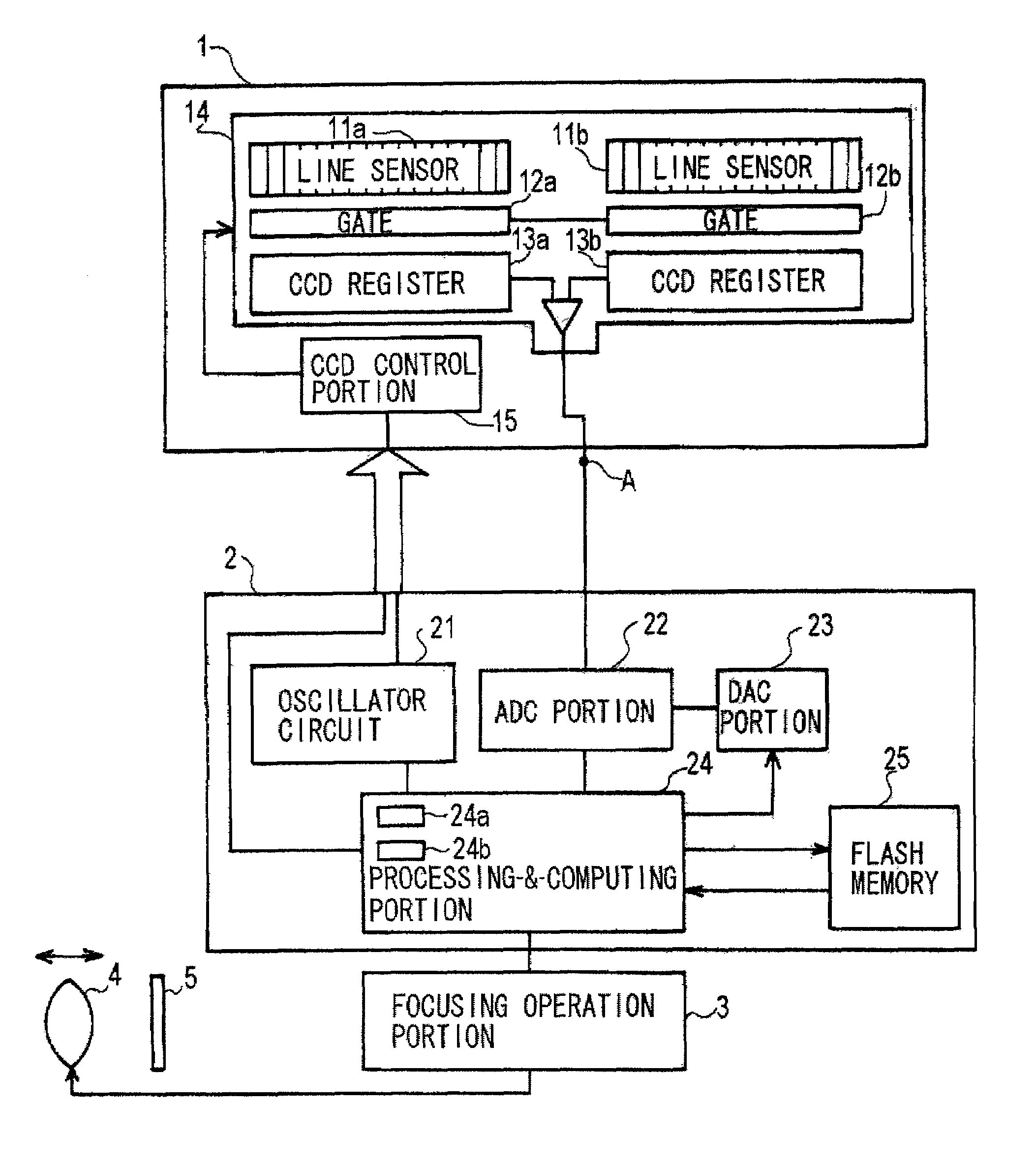
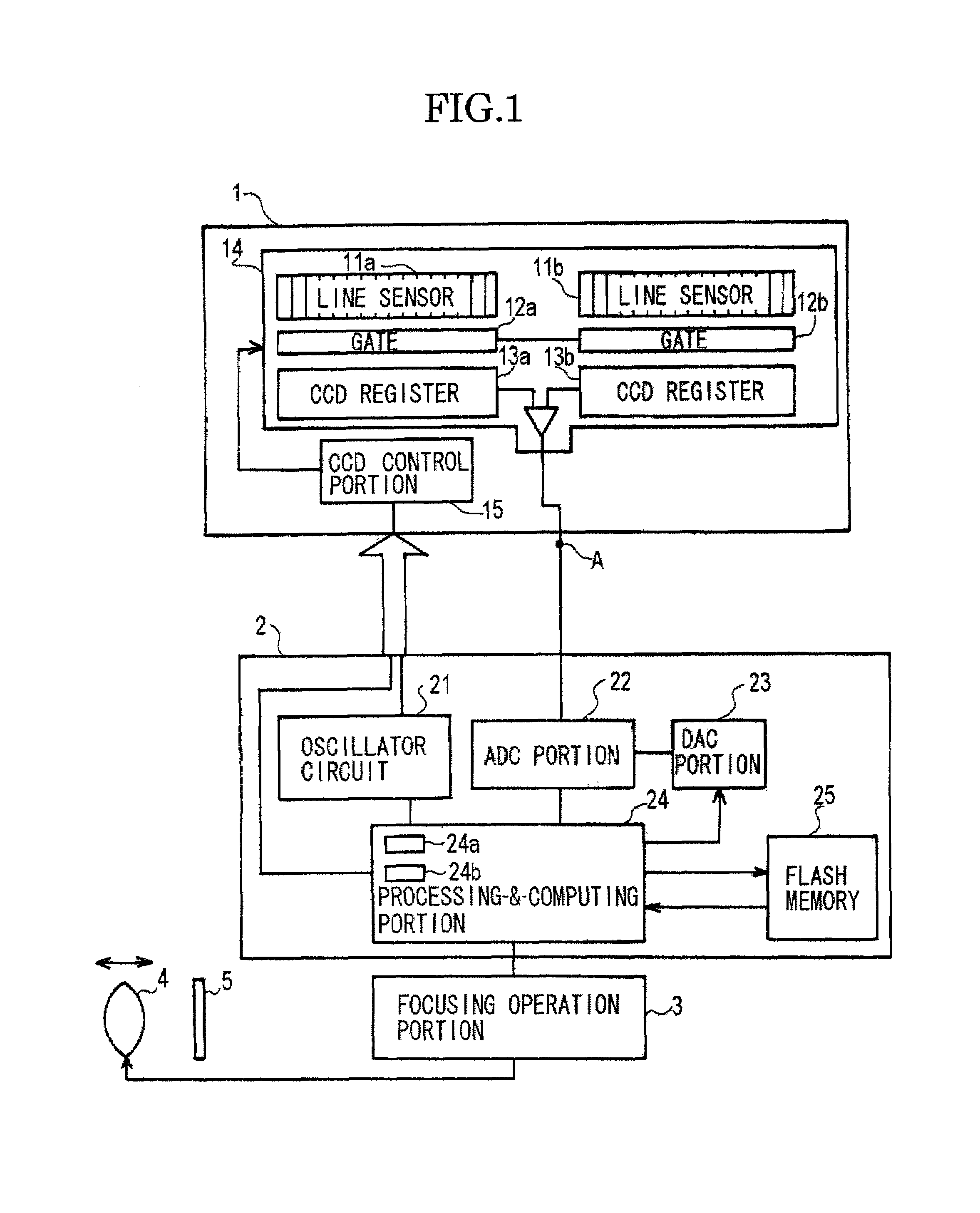
[0023]In FIG. 1, a CCD module 1 includes a CCD solid-state imaging device 14 and a CCD control portion 15 for controlling the operation of the imaging device 14. This imaging device 14 is fitted with a pair of photoelectric converter line sensor portions 1a, 11b, gateportions 12a, 12b, and CCD shift registers 13a, 13b.

[0024]The photoelectric converter line sensor portions (hereinafter referred to as the line sensor portions) 11a and 11b acting as sensor arrays are charge-accumulating light-sensitive elements, and each sensor portion has a plurality of pixels (light-sensitive cells). An image of a subject that is an object under measurement is focused onto the line sensor portions by a focusing optical system (not shown) such as lenses different from a photography lens, and these line sensor portions produce electric charge corresponding to the focused image.

[0025]The ope...


PUM


Abstract

An image signal output device for use in a passive range finder. The device can correct the sensitivities of sensor arrays according to the amount of incident light. The output device has line sensor portions that produce pixel outputs. An A / D converter portion A / D converts these pixel outputs. At this time, the A / D conversion range of the A / D converter portion is modified according to the difference in sensitivity between the line sensor portions.

Description

BACKGROUND OF THE INVENTION[0001]1. Field of the Invention[0002]The present invention relates to a method of outputting an image signal, device for outputting an image signal, rangefinder, and imaging device and, more particularly, to a method of outputting an image signal, device for outputting an image signal, rangefinder, and imaging device used in an autofocus camera or the like.[0003]2. Description of the Related Art[0004]Conventionally, a so-called passive rangefinder making use of an image signal output device having a plurality of arrays of light-receiving portions is available as disclosed, for example, in Japanese Patent Publication No. 67203 / 1991. The principle of range finding of this related art is briefly described by referring to FIG. 7. An image of a subject or an object under measurement 101 is focused onto sensor arrays 103a and 103b via light-receiving lenses 102a and 102b. Reference positions 104a and 104b (hereinafter referred to as “the pair of reference positi...

Claims


Application Information

Patent Timeline
Patent Type & Authority Patents(United States)
IPC IPC(8): H04N7/18G03B13/18G03B13/20G01B11/00G01C3/06G01J1/44G02B7/28G02B7/30G02B7/32G03B13/36H04N5/232
CPCH04N5/23212G02B7/32H04N23/67
Inventor SAITO, HIROYUKIGOHARA, AIJIRO
Owner SEIKO PRECISION CO LTD
Why Eureka
Try Eureka