Speckle sizing and sensor dimensions in optical positioning device

a technology of optical positioning and sensor dimensions, applied in the direction of static indicating devices, instruments, and reradiation, etc., can solve the problems of limiting the useful life of the device, prone to inaccuracy and malfunction, and low optical efficiency, and achieve relatively high image processing requirements

Active Publication Date: 2006-05-09
CYPRESS SEMICON CORP
View PDF66 Cites 38 Cited by
  • Summary
  • Abstract
  • Description
  • Claims
  • Application Information

AI Technical Summary

Problems solved by technology

One problem with mechanical mice is that they are prone to inaccuracy and malfunction after sustained use due to dirt accumulation and the like.
In addition, the movement and resultant wear of the mechanical elements, particularly the shaft encoders, necessarily limit the useful life of the device.
This technology typically provides good accuracy but suffers from low optical efficiency and relatively high image processing requirements.
Although a significant improvement over the conventional LED-based optical mice, these speckle-based devices have not been wholly satisfactory for a number of reasons.
In particular, mice using laser speckle have not demonstrated the accuracy typically demanded in state-of-the-art mice today, which generally are desired to have a path error of less than 0.5% or thereabout.

Method used


Image

  • Speckle sizing and sensor dimensions in optical positioning device
  • Speckle sizing and sensor dimensions in optical positioning device
  • Speckle sizing and sensor dimensions in optical positioning device

Examples


Embodiment Construction

Problems with Speckle Detection

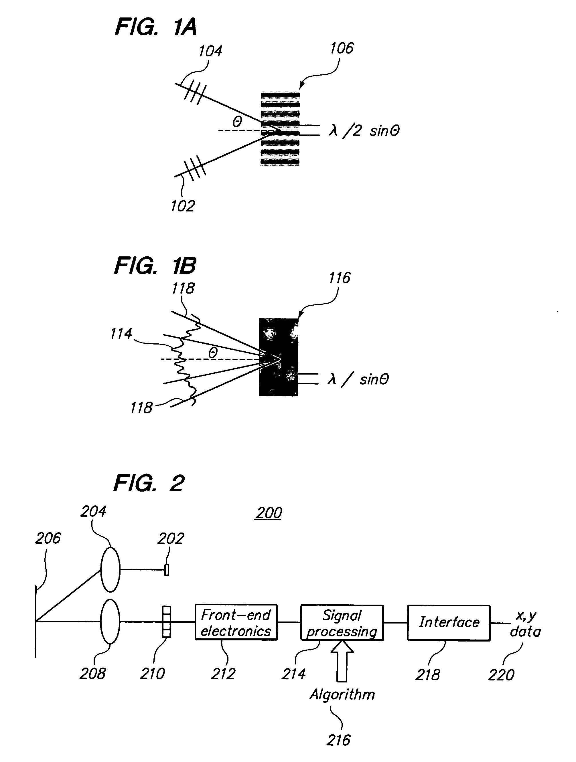
[0022]One problem with prior speckle-based OPDs is that speckles in the imaging plane are sometimes too small to be properly detected. This reduces the sensitivity and accuracy of the OPD. A related problem is that increasing the speckle size too much may substantially reduce the resultant signal-to-noise ratio.

[0023]Another problem with prior speckle-based OPDs is that the image analysis of the speckle pattern is sensitive to statistical fluctuations in the speckle pattern. Because speckles are generated through phase randomization of scattered coherent light, actual observed speckle can exhibit local patterns which do not have the expected average speckle size. In other words, while the speckles have a defined size and distribution on average, local patterns may be inconsistent with the average.

[0024]As discussed in detail below, one aspect of the present invention discloses a solution to both the above-discussed problems of speckle detection and sta...


PUM


Abstract

One embodiment relates to an optical displacement sensor for sensing transverse displacement of a data input device relative to a surface by determining displacement of optical features in a succession of frames. The sensor includes at least a coherent light source, illumination optics to illuminate a portion of the surface, imaging optics, and a first array of photosensitive elements having a periodic distance. The illuminator and the detector are configured to produce on the first array of photosensitive elements an intensity pattern of light reflected from the illuminated portion of the surface. The intensity pattern comprises a plurality of speckles having an average speckle diameter which is between one half and two times the periodic distance of the array.

Description

CROSS-REFERENCE TO RELATED APPLICATIONS[0001]The present application claims the benefit of U.S. provisional application No. 60 / 573,062, entitled “Speckle-based optical position sensing device having speckle size matched to a sensor dimension,” filed May 21, 2004, by inventors Clinton B. Carlisle, Jahja I. Trisnadi, Charles B. Roxlo, and David A. LeHoty. The disclosure of the aforementioned U.S. provisional application is hereby incorporated by reference in its entirety.[0002]The present application also claims the benefit of U.S. provisional application No. 60 / 573,075, entitled “Optical position sensing device having a detector array using different combinations of shared interlaced photosensitive elements,” filed May 21, 2004, by inventors David A. LeHoty, Douglas A. Webb, Charles B. Roxlo, Clinton B. Carlisle, and Jahja I. Trisnadi. The disclosure of the aforementioned U.S. provisional application is hereby incorporated by reference in its entirety.TECHNICAL FIELD[0003]The present...

Claims


Application Information

Patent Timeline
Patent Type & Authority Patents(United States)
IPC IPC(8): G01B9/02G09G5/08G01B11/02G01P3/36G01P3/68G06F3/03G06F3/033
CPCG01P3/36G06F3/0317G01P3/68
Inventor CARLISLE, CLINTON B.TRISNADI, JAHJA I.ROXLO, CHARLES B.LEHOTY, DAVID A.
Owner CYPRESS SEMICON CORP
Why Eureka
Try Eureka