
Switching electric source device

a technology of switching electric source and output voltage, which is applied in the direction of dc-dc conversion, climate sustainability, power conversion systems, etc., can solve the problems of deteriorating detection accuracy of detection circuit with respect to output voltage, and achieve the elimination of disturbance of circuit operation of switching electric source devices, simple configuration, and easy control

Active Publication Date: 2006-05-09
MURATA MFG CO LTD
View PDF6 Cites 13 Cited by
  • Summary
  • Abstract
  • Description
  • Claims
  • Application Information

AI Technical Summary

Benefits of technology

The present invention provides a switching electric source device with a transformer, a main switching element, a secondary rectifying smoothing circuit, and a detection circuit for indirectly detecting the output voltage from the secondary winding. The device includes a first synchronous rectifier and a second synchronous rectifier connected in parallel with the secondary winding. The first synchronous rectifier control circuit detects the output voltage and controls the switch on-off operation of the main switching element to stabilize the output voltage. The detection circuit uses a DC cut capacitor and a rectifying element connected in series with the DC cut capacitor to prevent current flow through the body diode of the first synchronous rectifier. The first synchronous rectifier control circuit also includes a circuit with a resistor and a rectifying element connected in parallel to control the timing of the first synchronous rectifier switch-on during the off-period of the main switching element. The device can provide a stable output voltage regardless of variations in input voltage and temperature. The off-control circuit discharges the electric charges stored between the gate-source of the first synchronous rectifier to eliminate circuit operation disturbances. The electric source for the first synchronous rectifier control circuit can include a winding or a choke coil for smoothing the power output. The device can enhance the reliability of the switching electric source device and improve the detection accuracy of the output voltage.

Problems solved by technology

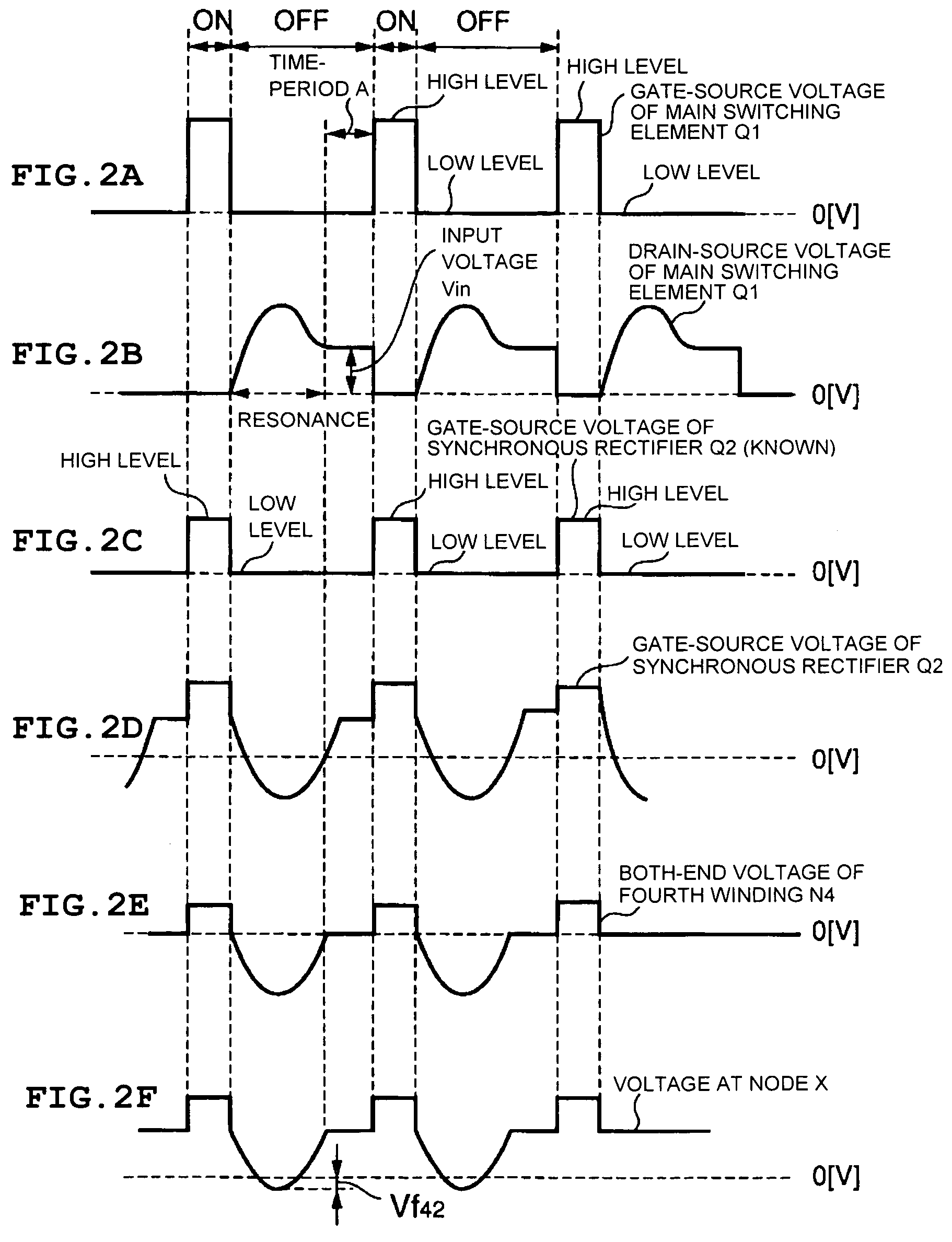
Accordingly, a problem in that the detection accuracy of the detection circuit with respect to the output voltage is deteriorated during the time period A can be solved.

Method used


Image

  • Switching electric source device
  • Switching electric source device
  • Switching electric source device

Examples


Embodiment Construction

[0040]Hereinafter, preferred embodiments according to the present invention will be described with reference to the drawings.

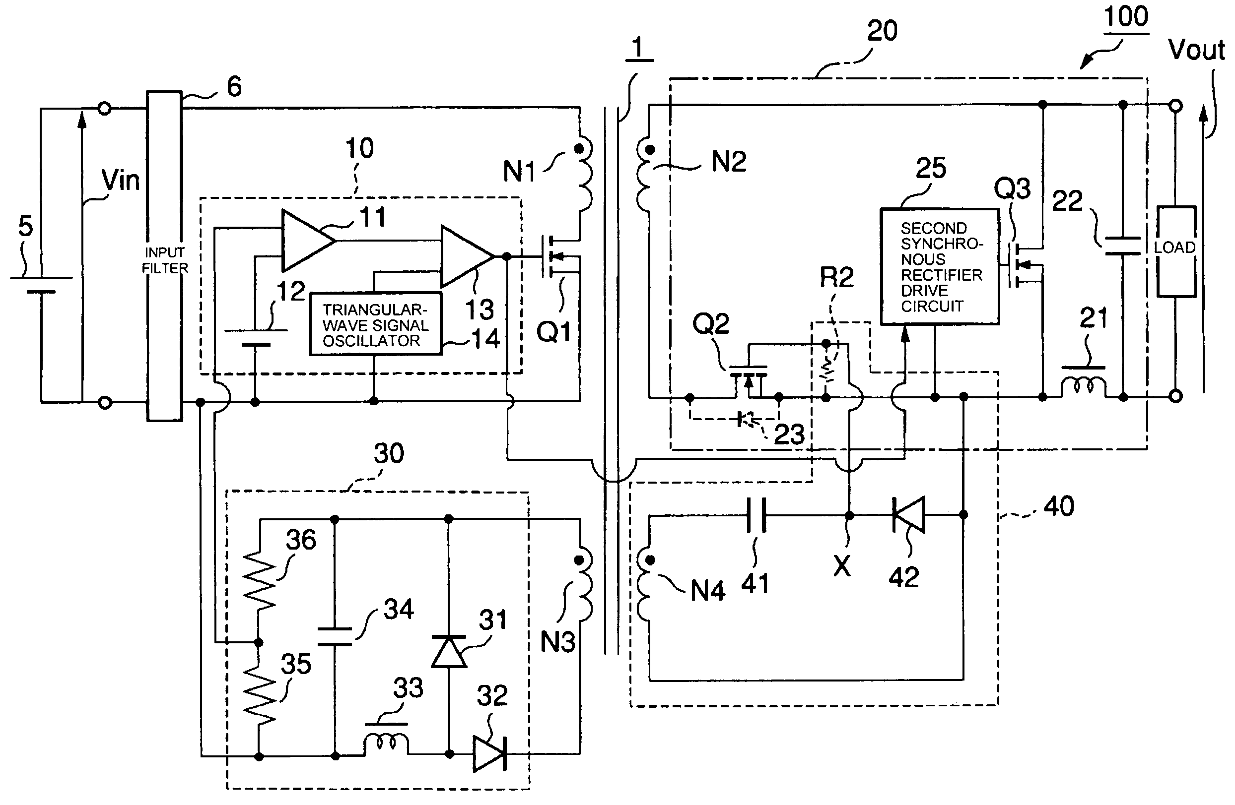
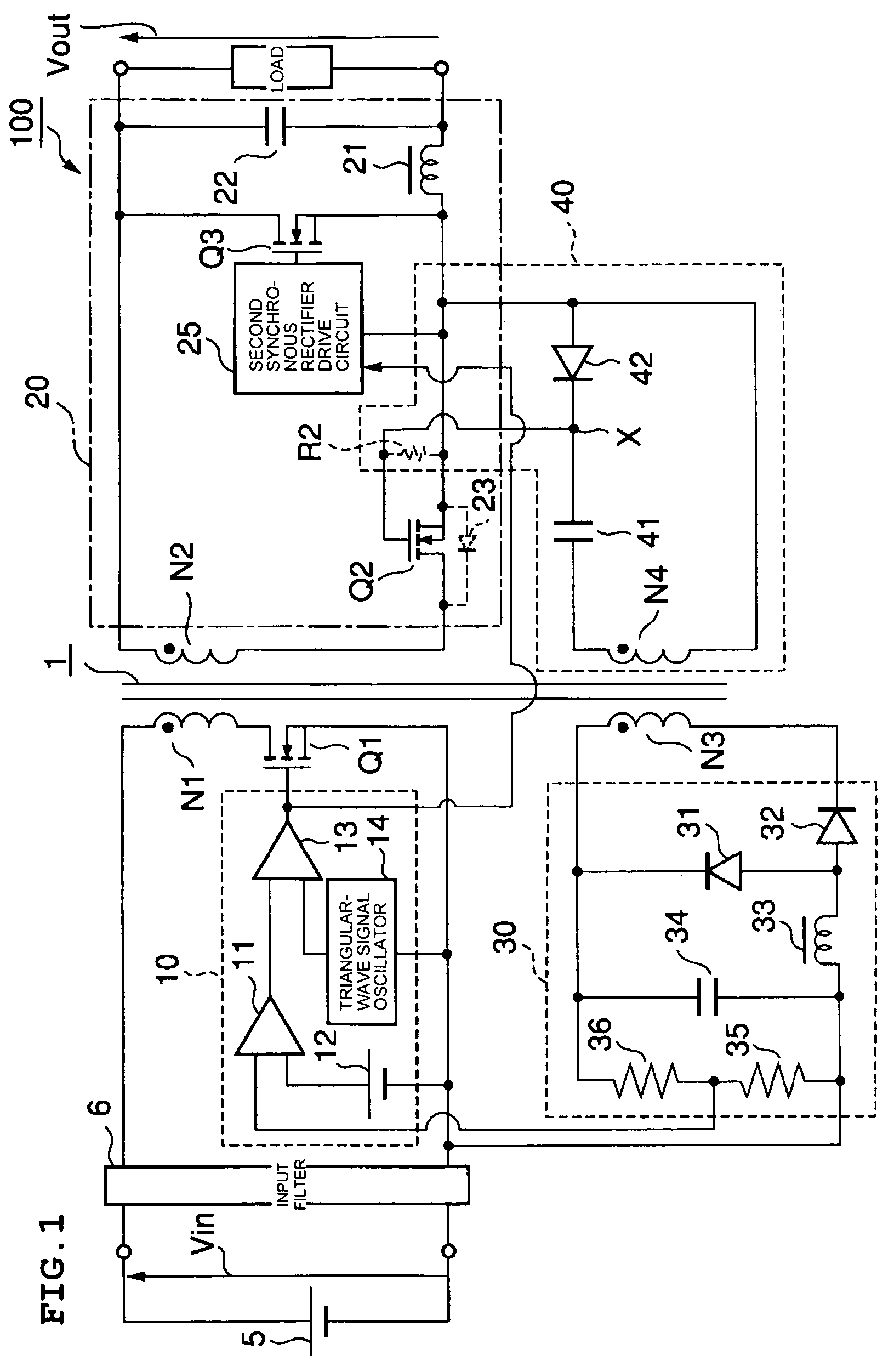
[0041]FIG. 1 shows the main circuit components of a switching electric source device according to a first preferred embodiment of the present invention. In the description of the first preferred embodiment, the same components as those of the switching electric source device 200 shown in FIG. 9 are designated by the same reference numerals, and the description thereof is not repeated.

[0042]The switching electric source device 100 according to the first preferred embodiment includes of a forward-type DC—DC converter. In the switching electric source device 100, a transformer 1 is provided with a fourth winding N4 in addition to a primary winding N1, a secondary winding N2, and a third winding N3.

[0043]A circuit including a DC-cut capacitor 41 and a diode 42 as a rectifying element connected in series is connected in series with the fourth winding N4 with the di...


PUM


Abstract

A switching electric source device includes a first synchronous rectifier control circuit, which detects the resonance state developed based on the exciting energy of the primary winding after the main switching element switches off, and causes a first synchronous rectifier to switch on earlier during the time period from the completion of the resonance state to the switching on of the main switching element. Thus, the first synchronous rectifier switches on during the time period, and thus, current is prevented from flowing through a body diode, so that a voltage caused by the voltage drop in the body diode is prevented from being induced in the secondary winding and the third winding. As a result, variations in the output voltage, which is caused by the induced voltage of the third winding, can be prevented. The output voltage can be stabilized.

Description

BACKGROUND OF THE INVENTION[0001]1. Field of the Invention[0002]The present invention relates to a switching electric source device including a transformer and a circuit for rectifying electric power output from a secondary winding of the transformer by use of a synchronous rectifier.[0003]2. Description of the Related Art[0004]A switching electric source device has been proposed which is provided with a detection circuit for indirectly detecting an output voltage, and controls a main switching element based on detection results by the detection circuit according to a PWM system (e.g., see Japanese Unexamined Patent Application Publication No. 2001-25245 (Patent Document 1)). FIG. 9 shows an example of a circuit configuration of major components of the switching electric source device having the detection circuit described above.[0005]The switching electric source device 200 contains a transformer 1. A main switching element (MOSFET) Q1 is connected to the primary winding N1 of the ...

Claims


Application Information

Patent Timeline
Patent Type & Authority Patents(United States)
IPC IPC(8): H02M3/335H02M3/28
CPCH02M3/33592Y02B70/1475Y02B70/10H02M3/28
Inventor NAGAI, JUNTSUJI, HITOSHI
Owner MURATA MFG CO LTD
Learn More