Optical transmission system, fec multiplexer, fec multiplexer/separator, and error correction method

a transmission system and optical transmission technology, applied in transmission monitoring, instruments, coding, etc., can solve the problems of increasing the ratio of redundant information to information data, the conventional optical transmission system, and the amount of deterioration of optical transmission characteristics with an increase in ra

Inactive Publication Date: 2006-05-09
MITSUBISHI ELECTRIC CORP
View PDF10 Cites 26 Cited by
  • Summary
  • Abstract
  • Description
  • Claims
  • Application Information

AI Technical Summary

Problems solved by technology

However, the conventional optical transmission system has the following problems.
On the other hand, when the code length of the error correction code is reduced, a ratio of redundant information to information data increases.
For this reason, in the conventional optical transmission system, even though the code length of an error correction code is reduced to maintain error correction capability, an amount of deterioration of optical transmission characteristics is increased with an increase in rate, a long-distance / large-capacity optical transmission system having desired quality cannot be structured.

Method used


Image

  • Optical transmission system, fec multiplexer, fec multiplexer/separator, and error correction method
  • Optical transmission system, fec multiplexer, fec multiplexer/separator, and error correction method
  • Optical transmission system, fec multiplexer, fec multiplexer/separator, and error correction method

Examples


first embodiment

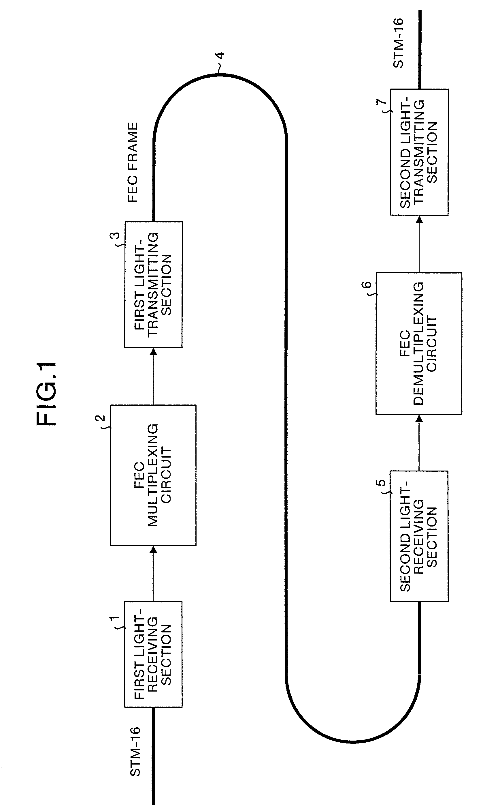
[0032]FIG. 1 is a diagram showing the configuration of an optical transmission system according to the present invention. In FIG. 1, reference numeral 1 denotes a first light-receiving section, reference numeral 2 denotes an FEC multiplexing circuit, reference numeral 3 denotes a first light-transmitting section, reference numeral 4 denotes a optical transmission path, reference numeral 5 denotes a second light-receiving section, reference numeral 6 denotes an FEC demultiplexing circuit, and reference numeral 7 denotes a second light-transmitting section.

[0033]In this optical transmission system, the first light-receiving section 1 receives an STM-16 optical signal, converts the optical signal into an electric signal, and outputs the electric signal to the FEC multiplexing circuit 2. The FEC multiplexing circuit 2 demodulates the received electric signal from the first light-receiving section 1, performs processes such as insertion of OH information and FEC encoding, and performs mu...

second embodiment

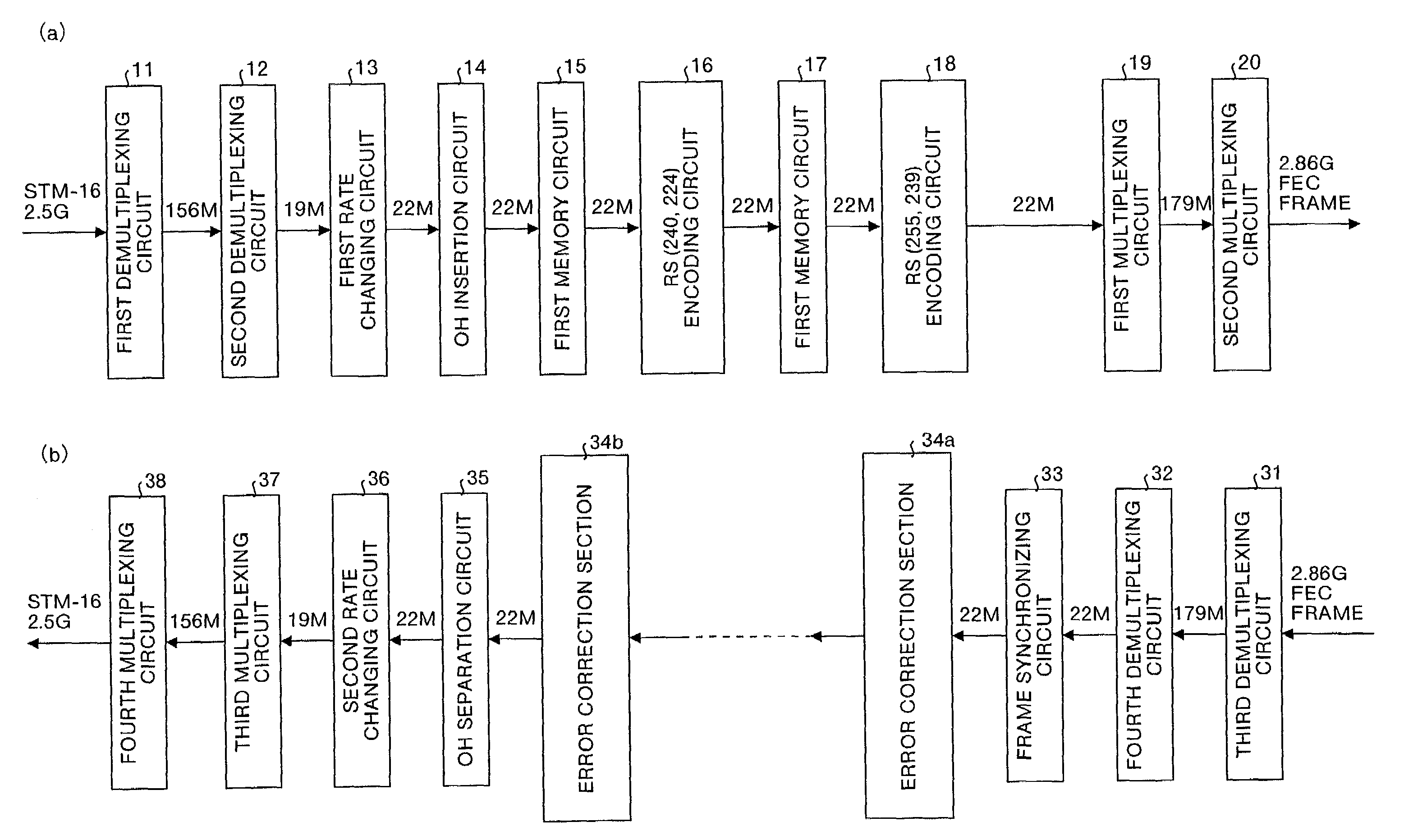
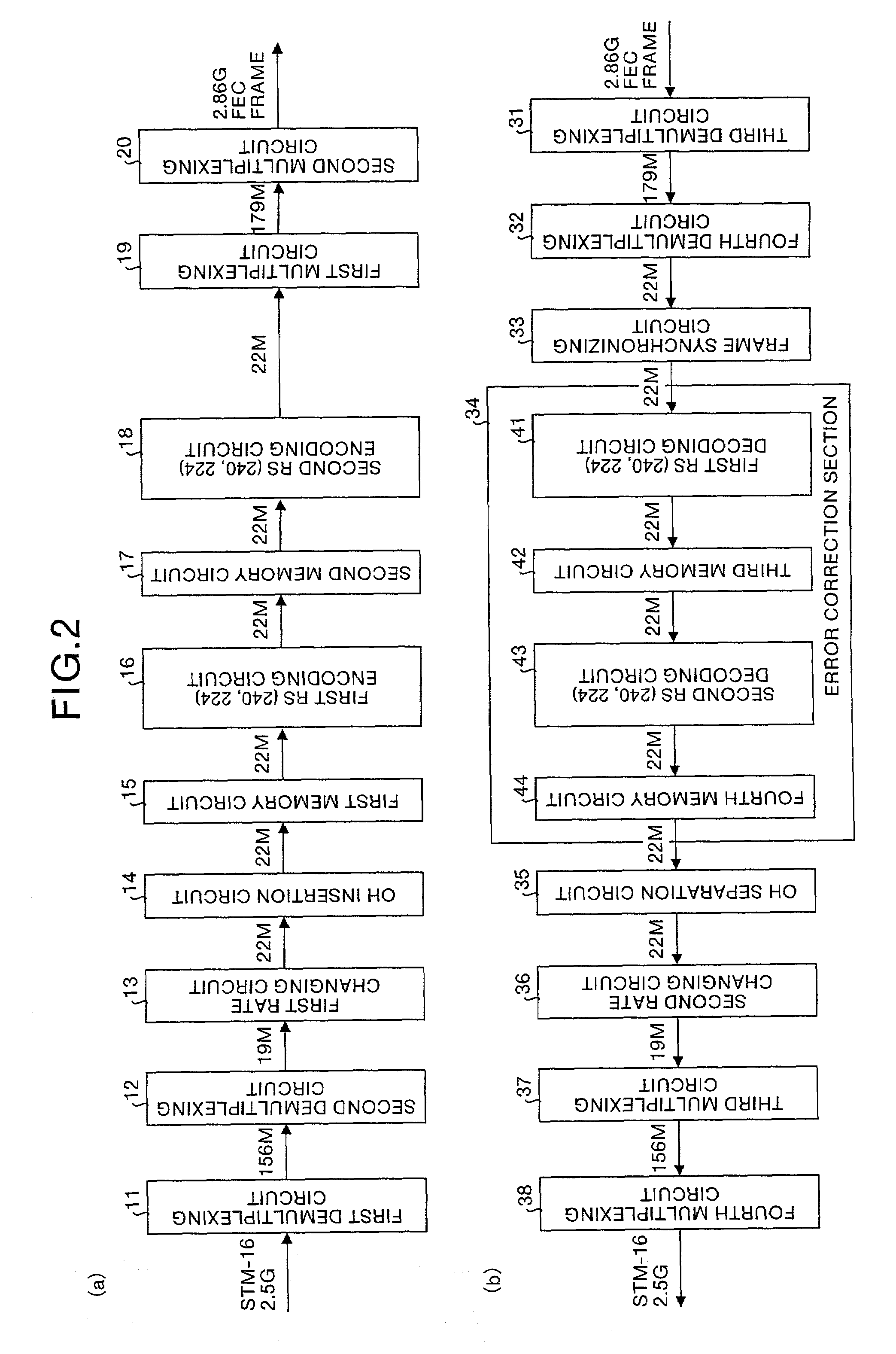
[0059]FIG. 6 includes diagrams showing the configurations of an FEC multiplexing circuit 2 (see FIG. 6(a)) and an FEC demultiplexing circuit (see FIG. 6(b)) in the optical transmission system (see FIG. 1) described above as a second embodiment. In FIG. 6, each reference numeral 34a, 34b denotes an error correction section. In the second embodiment, a plurality of error correction sections 34 each arranged in the FEC demultiplexing circuit 6 are arranged one after the other. The same reference numerals as in the first embodiment described above denote the same parts in second embodiment, and a description thereof will be omitted.

[0060]In the second embodiment, the process performed by the error correction section is repeated plural times. As a result, error correction capability can be considerably improved in comparison with the first embodiment. In the second embodiment, a long-distance / large-capacity optical transmission system can be easily structured without changing the configu...


PUM


Abstract

An FEC multiplexing circuit (2) has a configuration in which a first memory circuit (15) is arranged on the input stage of a first RS encoding circuit (16), a second memory circuit (17) is arranged on the input stage of a second RS encoding circuit (18), error correction encoding is performed by a combination of different data having two directions, and thereafter, error correction codes are multiplexed to generate an FEC frame. On the other hand, an FEC demultiplexing circuit (6) has a configuration in which a third memory circuit (42) is arranged on the output stage of a first RS decoding circuit (41), a fourth memory circuit (44) is arranged on the output stage of a second RS decoding circuit (43), error correction is performed by a combination of different data having two directions, and, thereafter, parallel data read from the fourth memory circuit (44) are multiplexed to reproduce original information data.

Description

TECHNICAL FIELD[0001]The present invention relates to an optical transmission system that corrects bit errors using FEC (For Error Correction) method. Particularly, this invention relates to an optical transmission system which realizes long-distance and large-capacity transmission by performing error correction using FEC method, an FEC multiplexing device that is a part of the optical transmission system, an FEC demultiplexing device, and a method of correcting error.BACKGROUND ART[0002]A conventional optical transmission system will be described below. As a conventional optical transmission system using FEC, a system achieved by a combination of an FEC multiplexing device and an FEC demultiplexing device described in ITU-T Recommendation G. 975 is known. FIG. 7(a) shows the configurations of the FEC multiplexing device, and FIG. 7(b) shows the configurations of the FEC demultiplexing device described in the above reference.[0003]In FIG. 7(a), reference numeral 101 denotes a first ...

Claims


Application Information

Patent Timeline
Patent Type & Authority Patents(United States)
IPC IPC(8): H04B10/00G06F11/10H03M13/03H03M13/15H03M13/29H03M13/33H04L1/00
CPCH03M13/03H03M13/15H03M13/1515H03M13/29H04L1/0071H04L1/0041H04L1/005H04L1/0057H04L1/0066H03M13/2909
Inventor KUBO, KAZUOYOSHIDA, HIDEOICHIBANGASE, HIROSHI
Owner MITSUBISHI ELECTRIC CORP
Why Eureka
Try Eureka