

Fading frequency estimating apparatus
a frequency estimation and fading technology, applied in the direction of amplitude demodulation, transmission monitoring, line-fault/interference reduction, etc., can solve the problems of insufficient accuracy of fading pitch detecting apparatus and portable information terminal, inability to use radio transmission systems, inability to obtain fading pitch with sufficient accuracy, etc., to achieve quick and accurate estimation of fading frequency
- Summary
- Abstract
- Description
- Claims
- Application Information
AI Technical Summary
Benefits of technology
Problems solved by technology
Method used
Image

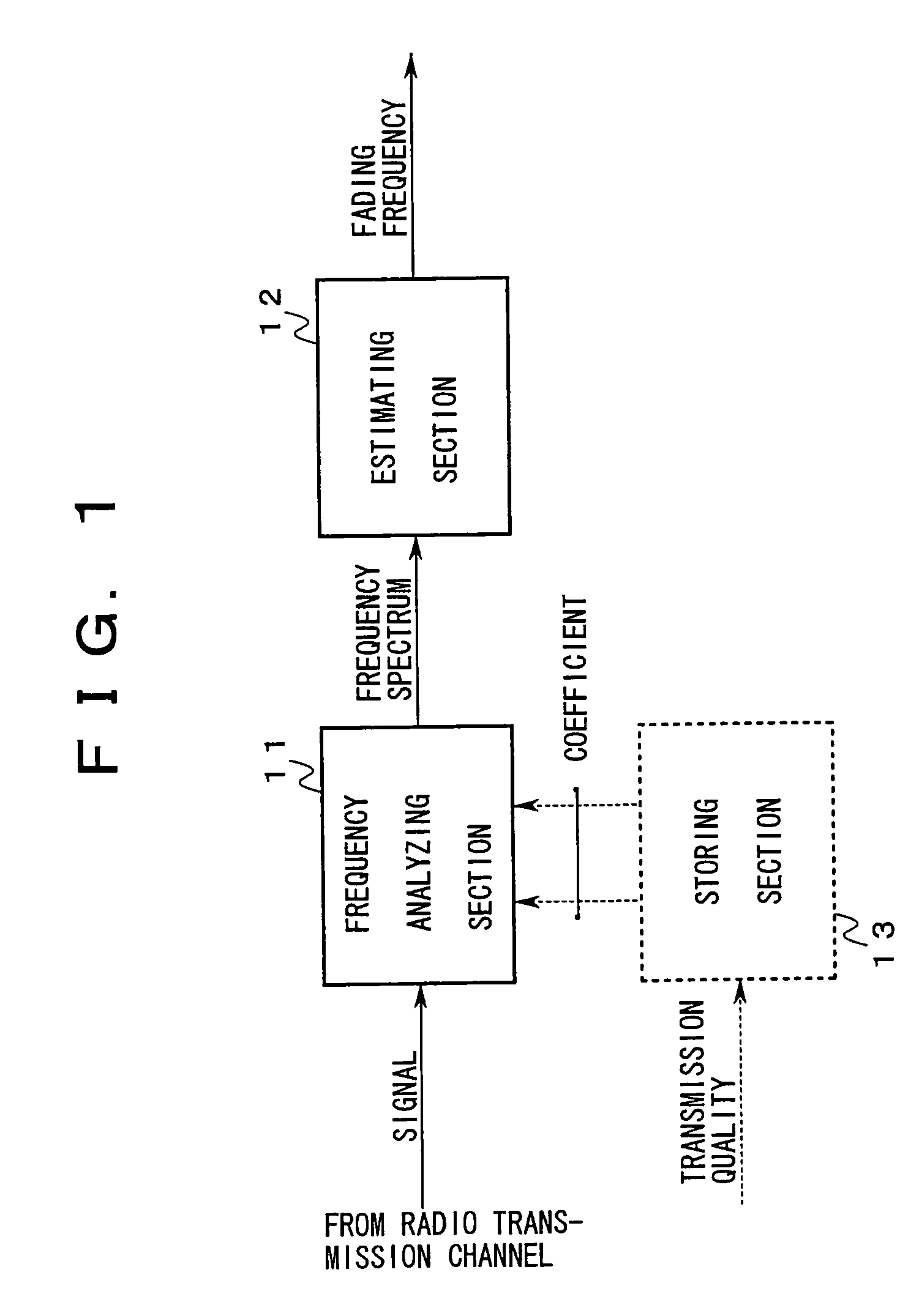
Examples
first embodiment
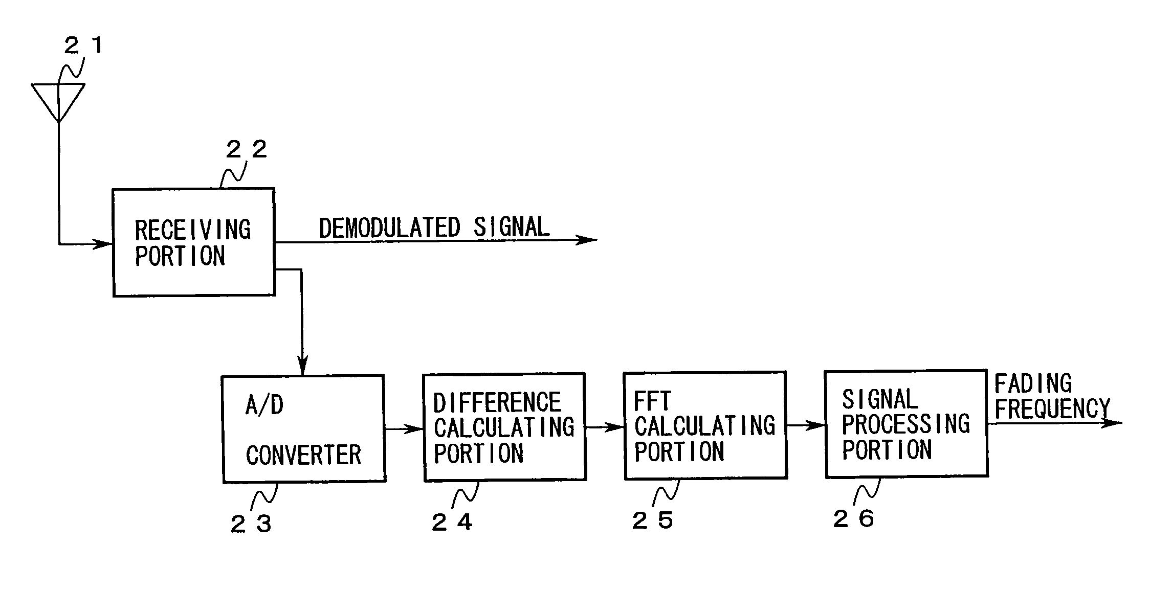
[0197]FIG. 5 is a schematic diagram showing first and third embodiments of the present invention.
[0198]In the drawing, a feeding point of an antenna 21 is connected to an input of a receiving portion 22. A demodulated signal is obtained from one output of the receiving portion 22. Another output of the receiving portion 22 is connected to an input of a signal processing portion 26 through an A / D converter 23, a difference calculating portion 24, and an FFT calculating portion 25 that are cascade-connected. A fading frequency is obtained from an output of the signal processing portion 26.
[0199]FIG. 6A and FIG. 6B are schematic diagrams describing an operation of the first embodiment. Next, with reference to FIG. 5 and FIGS. 6A and 6B, the operation of the first embodiment will be described.
[0200]The receiving portion 22 heterodyne-detects (homodyne-detects) a received wave that arrives at the antenna 21 through a particular radio channel formed in accordance with the CDMA system and ...
second embodiment
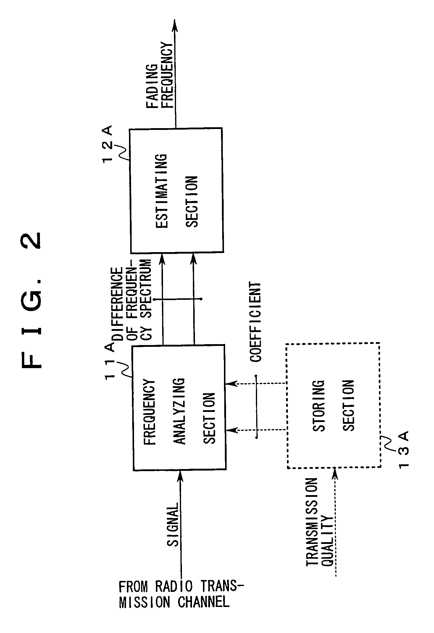
[0217]FIG. 7 is a schematic diagram showing a second embodiment of the present invention.
[0218]According to this embodiment, a weighted difference calculating portion 31 is disposed instead of the difference calculating portion 24.
[0219]Next, with reference to FIG. 7, an operation of the second embodiment of the present invention will be described.
[0220]This embodiment has a feature of which the weighted difference calculating portion 31 performs the following process to obtain a sequence Δ of differences.
[0221]Like the first embodiment, the weighted difference calculating portion 31 simultaneously captures two sequences “A1i” and “A2i” of amplitudes of two windows that satisfy all the window conditions and that differ on the time axis.
[0222]According to the first embodiment, in a low band of a frequency spectrum of which the Fast Fourier Transform is performed for the sequence Δ of differences, it is difficult to distinguish a variation component of an amplitude superimposed onto t...
third embodiment
[0234]Next, with reference to FIG. 5, an operation of a third embodiment of the present invention will be described.
[0235]This embodiment has a feature of which the signal processing portion 26 performs the following process.
[0236]The signal processing portion 26 determines a frequency slot whose power is larger than any other adjacent frequency slots of a frequency spectrum obtained by the FFT calculating portion 25 and whose relative value is the maximum in powers of these adjacent frequency slots instead of the foregoing frequency slot.
[0237]In addition, the signal processing portion 26 estimates a frequency fd at a center point between the highest frequency and the lowest frequency of the determined frequency slot on the frequency axis to be a fading frequency.
[0238]In other words, the center frequency of the frequency slot that is closest to a band of which a power change rate is the maximum on the frequency axis and whose power is the maximum is estimated to be a fading freque...
PUM
 Abstract
Description
Claims
Application Information