Method and apparatus for charging oil into fluid-dynamic-pressure bearings, spindle motor utilizing fluid-dynamic-pressure bearings, and signal record-and-playback device utilizing fluid-dynamic-pressure bearings

a technology of fluid-dynamic bearings and fluid-dynamic bearings, which is applied in the direction of sliding contact bearings, manufacturing tools, instruments, etc., can solve the problems of inability to wipe up, far and away more complicated work, and inability to use the first oil-charging method, etc., to achieve accurate charging of bearings, more economically and easily

Inactive Publication Date: 2006-05-16
NIDEC CORP
View PDF10 Cites 9 Cited by
  • Summary
  • Abstract
  • Description
  • Claims
  • Application Information

AI Technical Summary

Benefits of technology

[0018]An object of the present invention is to render a method of manufacturing fluid-dynamic-pressure bearings of the full-filled type that enables accurately charging the bearings with a preestablished volume of oil. Another object of the present invention is furthermore to render a method of manufacturing fluid-dynamic-pressure bearings of the full-filled type that by excluding process steps that involve worker intervention enables charging the bearings with a preestablished volume of oil more economically and easily.
[0020]As given by this manufacturing method, because the amount of oil that is injected at one time can be reduced by dividing the oil charging into two or more cycles, oil enters the bearing interior smoothly replacing residual air bubbles, which keeps incidents of splashing oil that follow on the bursting of air bubbles under control. This enables omitting or otherwise simplifying the manpower-expending process step of wiping up oil splashes. Consecutive to the injection operation running, partial air is introduced into the vacuum chamber (pressure-restoring operation), which applies pressure to the injected oil, forcing it into the interior of the bearing gap.
[0021]The fact that the injection operation is performed a number of times also enables the overall fill volume to be increased. Moreover, even in cases in which the oil fill volume exceeds the containable capacity of the taper seal area, performing the injection operation several or more times makes it possible to charge the requisite amount of oil into the bearings. The effectiveness of this is especially beneficial in cases where an oil-impregnable porous substance such as a sintered metal is utilized for the fluid-dynamic-pressure bearing sleeve-because the amount of oil that has to be charged into such bearings proves to be particularly large.
[0023]As given by this aspect, even in cases where the volume of oil injected is increased, going beyond what the bearings are designed for, the fact that by the manufacturing method of the present invention oil can be removed from the taper-seal area facilitates controlling the oil fill volume. Negative impact, such as leaking oil, associated with oil surplusage can be averted.
[0024]What is more, utilizing the method according to the present invention in either of the aspects described above facilitates charging the optimal amount of oil into fluid-dynamic-pressure bearings when batch-produced.

Problems solved by technology

Nevertheless, there are problems such as the following with oil-charging methods as described above.
In some cases, moreover, if there is a threaded hole or the like in the vicinity of the bearing opening, the spattered oil invades the threads, making wipe-up impossible.
Cases where the fluid-dynamic-pressure bearings have the structure given herein mean that this first oil-charging method cannot be used.
With the second oil-charging method on the other hand, the fact that the oil has to be injected into the bearings under a vacuum environment means that compared with cases where oil is injected under an atmosphere environment the work is far and away more complicated, wherein finely accurate control of the injection volume is difficult.
Incidents of oil leakage and shortening of bearing lifespan that originate in the amount of oil being too much or too little are therefore difficult to keep adequately under control.
Likewise, in recent years fluid-dynamic-pressure bearings utilizing sintered, oil-impregnated metals have appeared on the market in motors for hard-disk drives, but the fact that therein a section of the motor sleeve is composed of a porous, sintered metal substance means that the amount of oil to be injected is extremely large, exceeding the capacity of the taper-seal area.
An additional problem is that during volume production, with the individual fluid-dynamic-pressure bearings that are assembled not being identical, dimensional fluctuations will be present in the close-tolerance portions of the bearings, and therefore the optimal amount of oil with which they should be charged will vary subtly.
With other products, because the amount of oil will be greater than is optimal, when the products are built into a motor there is a chance that oil leaks will develop when the motor is spun.

Method used


Image

  • Method and apparatus for charging oil into fluid-dynamic-pressure bearings, spindle motor utilizing fluid-dynamic-pressure bearings, and signal record-and-playback device utilizing fluid-dynamic-pressure bearings
  • Method and apparatus for charging oil into fluid-dynamic-pressure bearings, spindle motor utilizing fluid-dynamic-pressure bearings, and signal record-and-playback device utilizing fluid-dynamic-pressure bearings
  • Method and apparatus for charging oil into fluid-dynamic-pressure bearings, spindle motor utilizing fluid-dynamic-pressure bearings, and signal record-and-playback device utilizing fluid-dynamic-pressure bearings

Examples


first embodiment

[0033]In the first embodiment, by carrying out oil injection and pressurization steps in two respective cycles, or more than that, the optimal amount of oil for the bearings is charged into them precisely and stably.

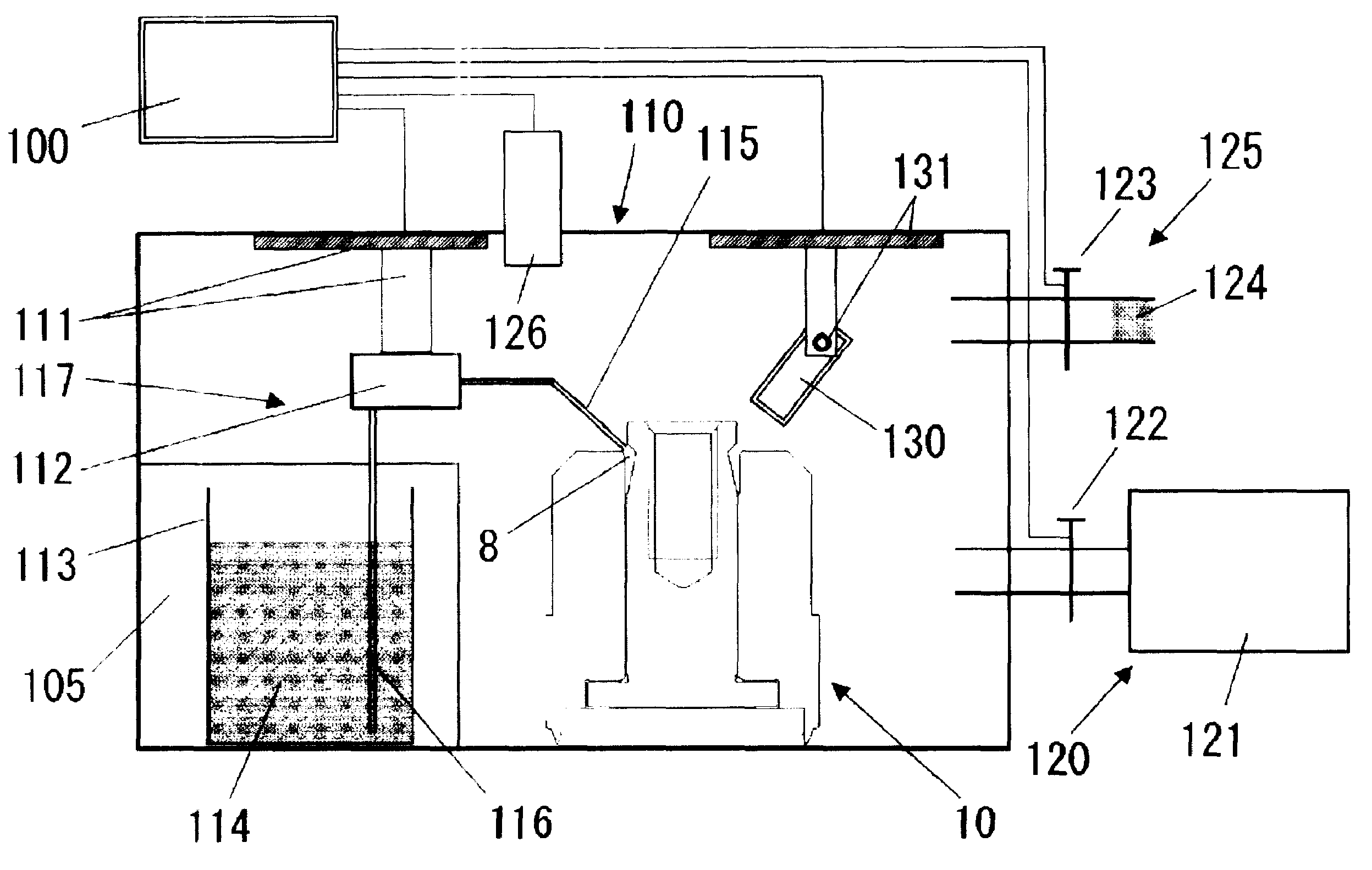
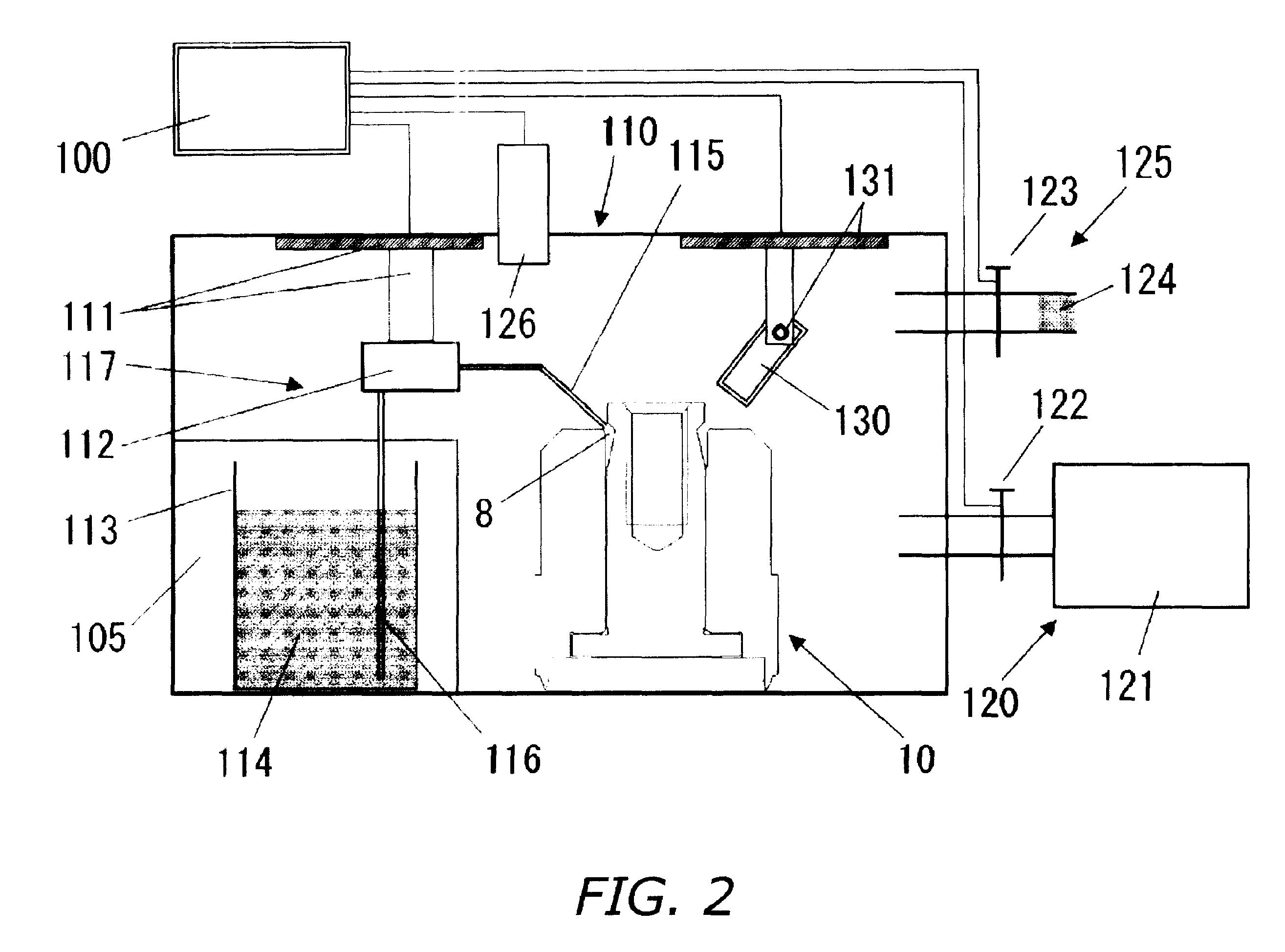
[0034]At first an oil-unfilled bearing unit 10 is inserted into a vacuum chamber 110 through a not-illustrated port in one of its side walls, and is set in place in a predetermined position within the vacuum chamber 110; the port is closed and the chamber is evacuated. In evacuating the chamber a leak valve 123 that makes up part of a gas-introducing mechanism 125 is closed, and the chamber is evacuated by an evacuating means 120. The evacuating means 120 is constituted from a rotary pump 121 and a valve 122; evacuation is controlled on / off by opening and closing the valve 122.

[0035]During evacuation pressure is monitored with a vacuum gauge 126, and after it reaches a first gas pressure P1 that has been determined in advance, the oil injection work is begun with the eva...

second embodiment

[0052]In the second embodiment, charging oil into the bearings is carried out by a program of injecting and pressurizing a third amount of oil that is greater than the preestablished volume of oil based on the value that the bearings are designed for, and of removing a fourth volume of oil that has been injected exceeding the preestablished volume. Precise, stable oil fill is thereby realized.

[0053]In the present embodiment a device furnished with an oil removal nozzle 140 and a mechanism 141 for adjusting its position (FIG. 3) is additionally installed in the oil-charging apparatus illustrated in FIG. 2. A slender metal tube such as a syringe needle, or else a brush or the like that adsorbs and removes oil can be utilized as the oil removal nozzle 140. Cases in which the oil is to be removed not by adsorption but by aspiration require installation of an aspiration device (not illustrated) for imparting aspirating force to the removal nozzle. Likewise, cases in which the oil is to b...


PUM

PropertyMeasurementUnit
pressureaaaaaaaaaa
pressureaaaaaaaaaa
gas pressureaaaaaaaaaa

Abstract

Manufacturing method enabling optimal volume oil-fill even where differing from bearing to bearing due to machining fluctuations in volume-production dynamic pressure bearings. In a first charging method, injection of oil is divided into two cycles. The first is carried out under reduced pressure, following which the pressure is raised a predetermined amount to force the oil into the bearing gap. The oil-fill status is thereupon checked, the shortage is reckoned, and in the second cycle the shortage is injected. In a second charging method, in a first cycle a surplus volume is injected under reduced pressure and the pressure is raised a predetermined amount to force the oil into the bearing gap. Following that, what is in excess of the appropriate amount is removed from the bearing. The first cycle of injection and the pressure elevation may be implemented multiple times, in between which repeat pressure-reduction can be carried out.

Description

BACKGROUND OF INVENTION[0001]1. Technical Field[0002]The present invention relates to fluid-dynamic-pressure bearings employed in signal record-and-playback devices in hard-disk drives and like apparatus, and to methods and equipment for manufacturing such bearings.[0003]2. Description of the Related Art[0004]Various fluid-dynamic-pressure bearings have been used to date in spindle motors employed in signal record-and-playback devices in hard-disk drives and like apparatus. “Fluid-dynamic-pressure bearings” are bearings in which a lubricating fluid such as oil is interposed between a shaft and a sleeve, wherein fluid pressure produced in the lubricating fluid is the bearing force.[0005]One example of a spindle motor employing conventional pressure bearings of this sort is illustrated in FIG. 1. In between the outer circumferential surface of a shaft 2 that forms a unit with a rotor 1, and the inner circumferential surface of a sleeve 3 through which the shaft 2 is passed free to rot...

Claims


Application Information

Patent Timeline
Patent Type & Authority Patents(United States)
IPC IPC(8): B21D53/10F16C33/10G11B19/20
CPCF16C17/107F16C33/103F16C33/107F16C41/008G11B19/2018Y10T29/53104F16C2370/12Y10T29/49639
Inventor HAYASHI, HIROYUKIYOSHIDA, TATSUYASUZUKI, YUZOKIMURA, TOSHIHIRO
Owner NIDEC CORP
Why Eureka
Try Eureka