
System for detecting sliding of a wheel travelling along a track

a technology for sliding and track, which is applied in the direction of television systems, locomotives, color televisions, etc., can solve the problems of excessive rail and wheel wear, derailment of the associate vehicle or even the entire train, and damage to rails and wheels

Active Publication Date: 2006-05-16
SIEMENS MOBILITY PTY LTD
View PDF24 Cites 2 Cited by
  • Summary
  • Abstract
  • Description
  • Claims
  • Application Information

AI Technical Summary

Benefits of technology

"The present invention provides a system for detecting when a wheel on a track slides or slips. This system uses a roller and a rotation sensor to detect the rotation of the roller when a wheel passes over it. By measuring the degree of rotation, the system can determine if the wheel is sliding or slipping. This information can be used to alert maintenance personnel or to prevent accidents. The system can also detect the direction in which the wheel passes over the roller, which can help with identifying the cause of the problem. Overall, the system provides a reliable and effective way to detect and address wheel sliding or slipping on a track."

Problems solved by technology

Sliding wheels lead to damaged rails and wheels.
Wheels that slide continuously can further lead to derailments of the associate vehicle or even the entire train.
Further, wheels with worn tread do not track properly on the rails and lead to excessive rail and wheel wear.
A major challenge in the design of equipment to detect slipping or sliding wheels is the need for relatively inexpensive equipment which will operate dependably in the intensely hostile environment close to rail wheels.
This type of system is vulnerable to dust and rain, and also requires prior information about the rail wheel diameter.
It is also difficult to apply to a number of vehicle designs where the wheel and axle rotation is difficult to detect visually.

Method used


Image

  • System for detecting sliding of a wheel travelling along a track
  • System for detecting sliding of a wheel travelling along a track
  • System for detecting sliding of a wheel travelling along a track

Examples


Embodiment Construction

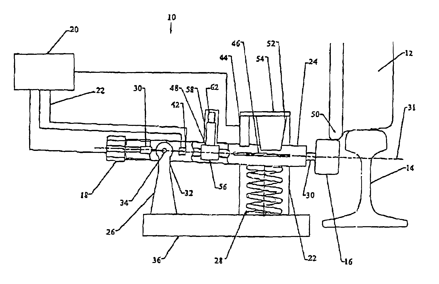
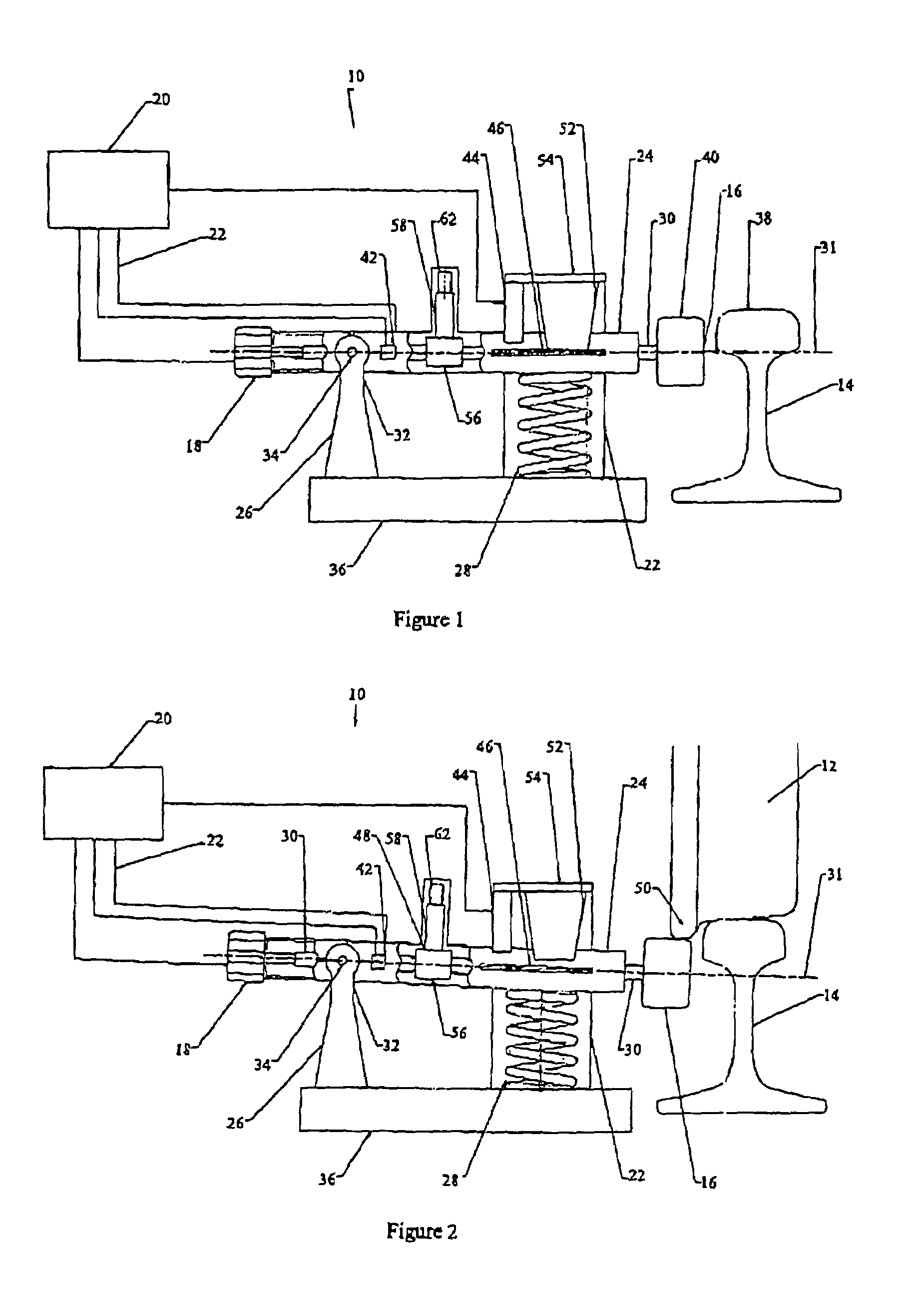
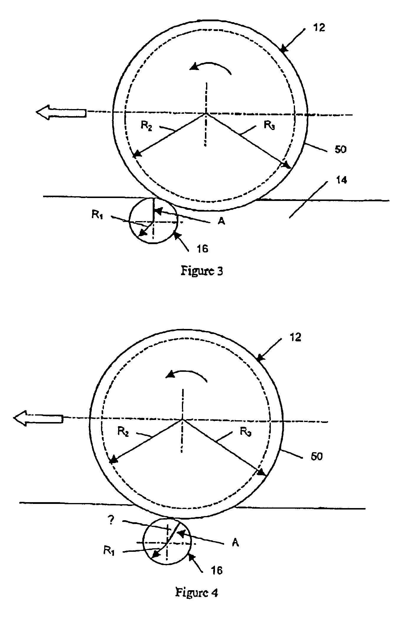
[0035]Referring to the accompanying drawings, and in particular FIGS. 1 and 2, a system 10 for detecting sliding of a wheel 12 on a track in the form of rail 14 comprises a roller 16 disposed adjacent the rail 14 so that a wheel 12 travelling along the rail 14 can engage the roller 16, and a rotation sensor in the form of a tachometer 18 (hereinafter referred to as “tacho 18”) associated with the roller 16 for providing a rotation signal representative of the degree of rotation of the roller. A processor in the form of a computer 20 receives the rotation signal from the tacho 18 and using an appropriate rotation algorithm calculates the degree of rotation of the roller 16. Thereafter, the computer 20 compares the degree of rotation with a predetermined range of roller rotations and provides a signal indicative of the wheel 12 sliding when the degree of rotation is outside the predetermined range. The rotation signal from the taco 18 may be transmitted by line (e.g. electrical or opt...


PUM

PropertyMeasurementUnit
radius R1aaaaaaaaaa
heightaaaaaaaaaa
heightaaaaaaaaaa

Abstract

A system 10 for detecting sliding of a wheel 12 on a rail 14 includes a roller 16 disposed adjacent the rail 14 so that a wheel 12 travelling along the rail 14 can engage the roller 16, and a tachometer 18 coupled with the roller 16 for providing a rotation signal representative of the degree of rotation of the roller. The system 10 includes a computer 20 which receives the rotation signal from the tachometer 18 and by using an appropriate rotation algorithm calculates the degree of rotation of the roller 16. The computer 20 then compares the degree of rotation with a predetermined range of roller rotations and, if the calculated degree of rotation of the roller is less than predicted by analysis, the apparatus 10 provides a signal indicative of the wheel 12 sliding.

Description

FIELD OF THE INVENTION[0001]The present invention relates to a system for detecting the sliding of a wheel travelling along a track, and in particular for detecting sliding of railway wheels. The invention further relates to a system for estimating tread wear on such wheels.BACKGROUND OF THE INVENTION[0002]Sliding of railway wheels travelling along a railway track occurs when the wheels on the corresponding rail vehicle are not rotating at the natural rotational speed equivalent to the vehicle's linear speed. When the wheels are braked either intentionally, or by a mechanical fault, beyond their limits of adhesion between the rails and the wheels, the wheels are said to be sliding.[0003]Sliding wheels lead to damaged rails and wheels. Wheels that slide continuously can further lead to derailments of the associate vehicle or even the entire train. Further, wheels with worn tread do not track properly on the rails and lead to excessive rail and wheel wear.[0004]A major challenge in th...

Claims


Application Information

Patent Timeline
Patent Type & Authority Patents(United States)
IPC IPC(8): G01N17/00B60T8/17G03B15/00B60T8/32B61C15/08G01M17/10G01P3/00G01P13/00G01P13/04G06G7/76H04N5/225H04N5/232
CPCB60T8/324B60T8/1705
Inventor BLAIR, JIM
Owner SIEMENS MOBILITY PTY LTD
Learn More