Quick connection for removably joining two pipes and use of such a connection

a technology of removable connection and connection, which is applied in the field of quick connection, can solve the problems of relative difficulty in maneuverability, dead volume between the valves, and difficult maneuverability of known connections

Active Publication Date: 2006-05-16
STAUBLI FAVERGES SA
View PDF10 Cites 51 Cited by
  • Summary
  • Abstract
  • Description
  • Claims
  • Application Information

AI Technical Summary

Benefits of technology

[0008]In addition, the invention makes it possible to minimize the dimensions of a connection according to the invention insofar as a member with transverse displacement necessitates less surface in order to be efficiently manipulated by a user than a sleeve such as the one known in the state of the art. In addition, the control effort which is exerted by the user on the control member is perpendicular to the axis of the connection, therefore with little risk of slippage.
[0009]Finally, because of surface abutment of the opposite surfaces of the fixed parts and of the mobile valves, the creation of a dead volume between the male and female elements is avoided, such a volume being capable of inducing leaks during the manipulation of the connection.
[0010]The connection of the invention therefore makes it possible efficiently to perform a triple function of double-closure, of easy manipulation and of tightness upon connection / disconnection, by a structure which is at the same time reliable, compact and economical.

Problems solved by technology

These connections present the drawback that they are relatively difficult to maneuver insofar as the locking of the male and female elements in fitted position is effected by balls mounted in the female element and and that are engaged in a retaining groove made on the outer radial surface of the male element.
As a result, these known connections are sometimes difficult to maneuver, particularly when the pipes to which they are connected contain fluids under relatively high pressure or when the rings are soiled by greasy products.
U.S. Pat. No. 5,494,074 discloses a connection of which the male and female elements are each provided with a valve whose projecting parts come into abutment on each other, with the result that a dead volume is created between the valves, which, when the connection is opened, induces leakages.
In addition, the elastic U-shaped blade used for locking the connection in fitted configuration is unreliable.

Method used


Image

  • Quick connection for removably joining two pipes and use of such a connection
  • Quick connection for removably joining two pipes and use of such a connection
  • Quick connection for removably joining two pipes and use of such a connection

Examples


Embodiment Construction

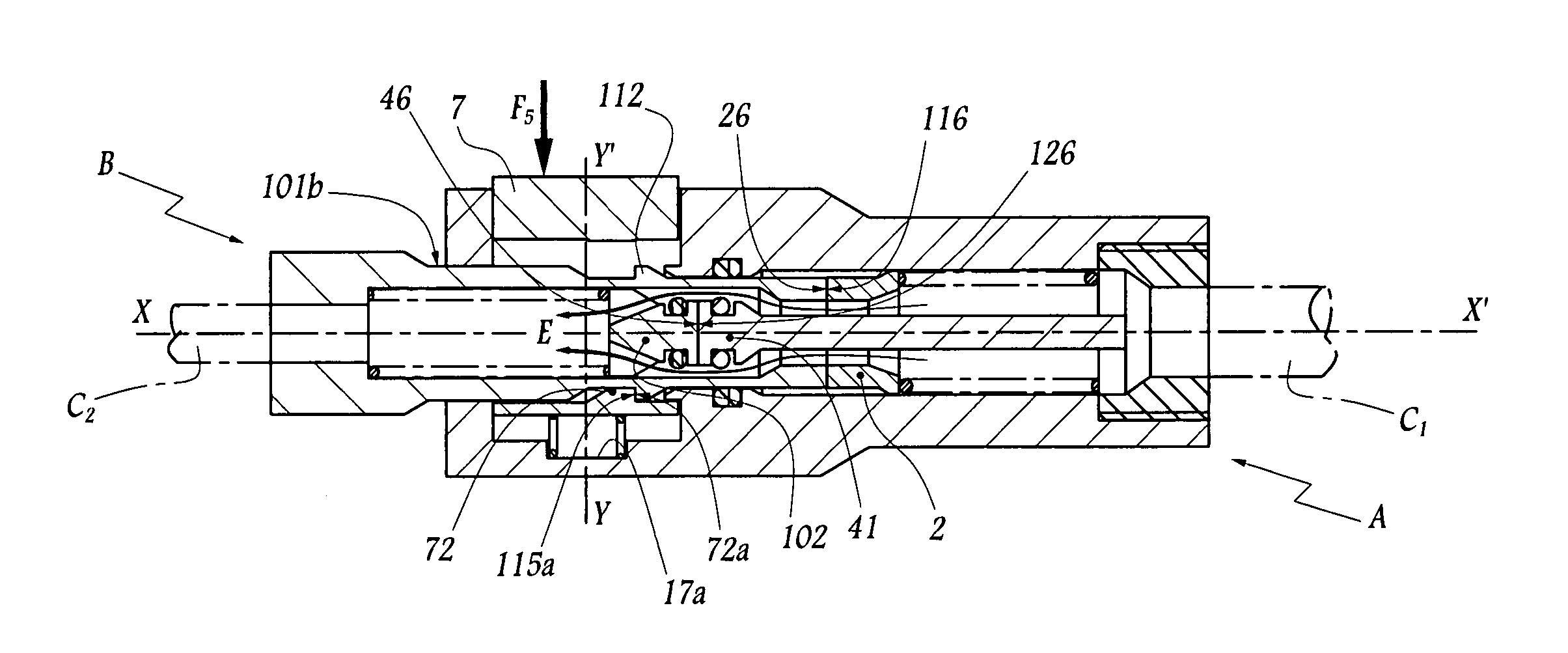
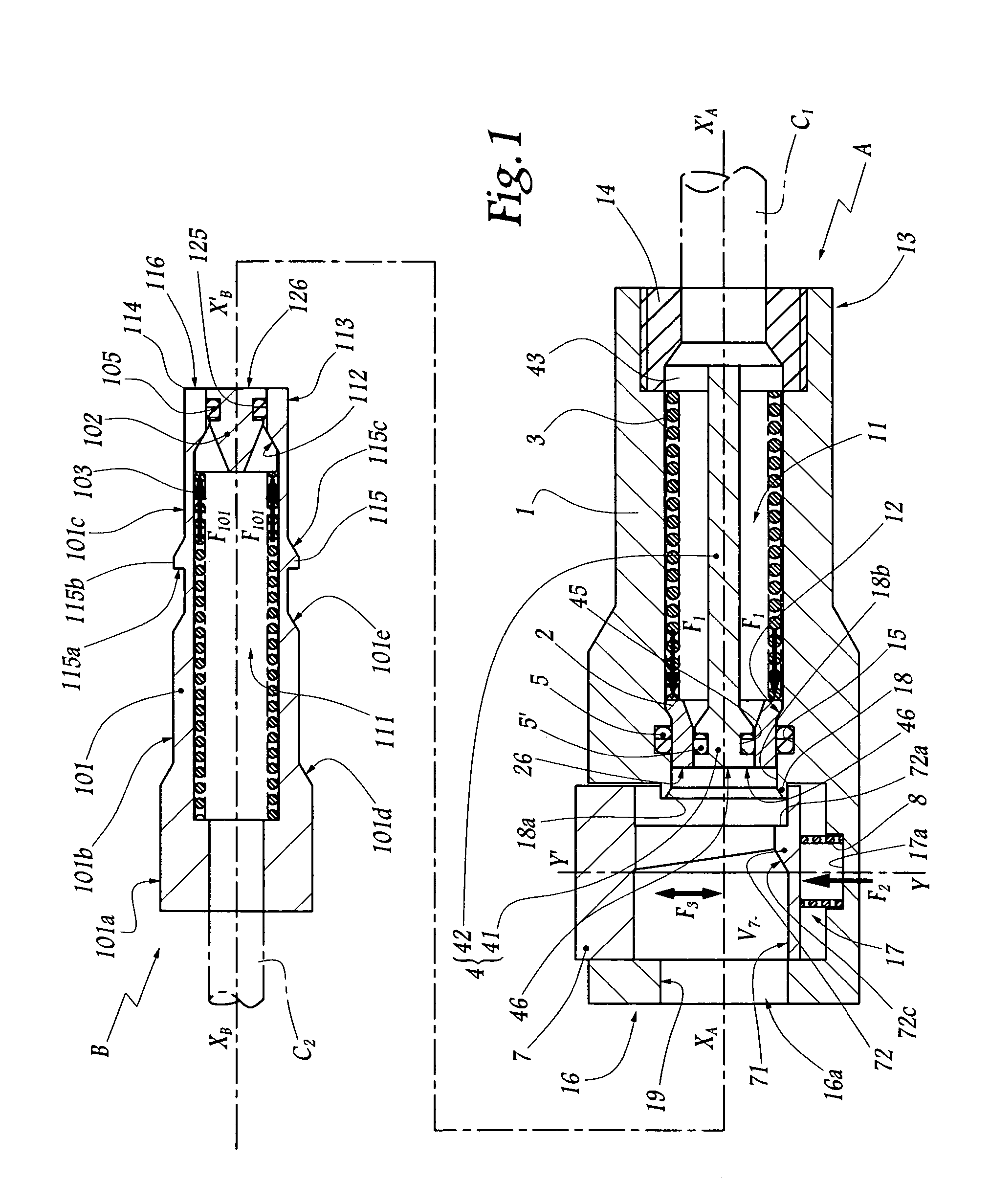
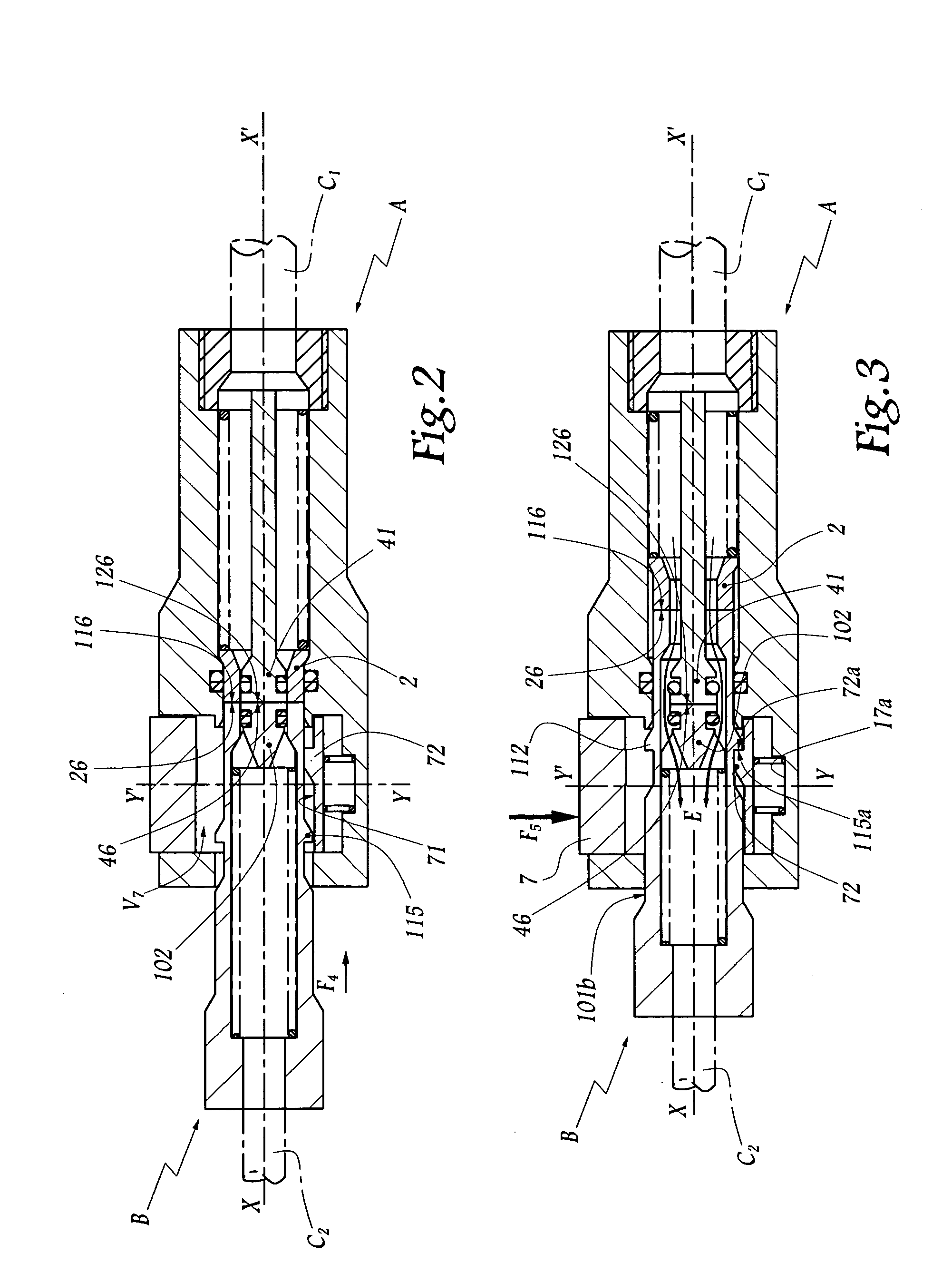
[0017]Referring now to the drawings, the connection or quick connect coupling shown in FIGS. 1 to 3 comprises a female element A and a male element or connector B, respectively connected to an upstream pipe C1 and to a downstream pipe C2. The upstream pipe C1 is, itself, connected to a source of fluid under pressure (not shown).

[0018]The outside shape of the body 1 of the female element A is cylindro-conical with circular base, centered on an axis XA–X′A which is also the longitudinal axis of a conduit 11 inside the body 1 and in which is disposed a valve 2 mobile along axis XA–X′A with respect to the body 1. This valve 2 is intended to come into abutment against a seat 12 formed by an inner truncated surface of the body 1. The valve 2 is subjected to an elastic effort or force F1 exerted by a spring 3, this effort F1 tending to apply it against the seat 12. The valve 2 is centered on a head 41 of a pusher element 4 of which the shank 42, which is in one piece with the head 41, exte...


PUM


Abstract

A quick connect coupling including male and female elements that are adapted to fit axially in each other and each includes a valve that is displaced to an open position by engagement by a fixed pusher part of each element when they are being fitted together. The female element is provided with a locking member in which a part of the male element is received and which is reciprocally movable in a radial direction with respect to an axis of fit of the elements between two positions in which the locking member respectively allows or opposes the separation of the male and female elements and wherein the engaging surfaces of the valves and pusher parts is such that no open volumes or voids are created therein in which a liquid may collect during assembly or disassembly of the male and female elements.

Description

BACKGROUND OF THE INVENTION[0001]The present invention relates to a quick connection for removably joining of pipes conveying fluid under pressure, as well as to a use of such a connection.BRIEF DESCRIPTION OF THE RELATED ART[0002]In the domain of connections, it is known, for example from FR-A-1 561 337, to provide in each element of a connection with a mobile valve elastically loaded or forced towards a position of closure of the flow through the corresponding element. Each of these valves is intended to be displaced, against the elastic load to which it is subjected, by a fixed part of the other element. This is generally referred to as a double-closure connection. Such connections have the advantage of limiting the risks of leakage to a maximum, insofar as the male element, on the one hand, and the female element, on the other hand, are open only when the act of fitting is sufficiently advanced to provoke the displacement of the afore-mentioned valves. These connections present ...

Claims


Application Information

Patent Timeline
Patent Type & Authority Patents(United States)
IPC IPC(8): F16L37/28F16L37/084F16L37/34
CPCF16L37/34F16L37/0841Y10T137/87949Y10T137/87965
Inventor TIBERGHIEN, ALAIN-CHRISTOPHE
Owner STAUBLI FAVERGES SA
Why Eureka
Try Eureka