Method for improving drilling depth measurements

a drilling depth and measurement method technology, applied in the field of drilling wellbores through the earth, can solve the problems of time and for determining the depth of drilling, the axial length of drilling string changes are not well-accounted for, and the measurement of drive vertical position is not ideal

Inactive Publication Date: 2006-05-16
HUTCHINSON MARK W
View PDF1 Cites 47 Cited by
  • Summary
  • Abstract
  • Description
  • Claims
  • Application Information

AI Technical Summary

Problems solved by technology

Systems known in the art for determining depth with respect to time, and for determining ROP have proven less than ideal.
One limitation of prior art depth measurement techniques using top drive (or kelly) vertical position measurements is that they do not account well for changes in axial length of the drill string as a result of changes in axial load on the drill string.
However, such methods only correct drill string length statically.
In many cases, the drilling progresses at such a high rate that drill string compression (shortening) due to increases in axial force applied to the drill string does not exactly correspond to the true change in the length of the drill string Depth measurements known in the art and made only from the vertical position measurements, even when such measurements are corrected for drill string loading, are thus subject to error.
ROP determination is directly related to depth measurement, and thus is correspondingly subject to error using depth measurement methods known in the art.
Another aspect of prior art data recording techniques is that there are not any well known, systematic methods for determining which data are more suitable for interpretation and analysis.
During the drilling process, the drill string and BHA may undergo shock, vibration, torsional oscillations or whirl.
Aside from the destructive nature of these modes of motion, data recorded during times when the drill string or BHA undergo such motion may be less reliable than when drilling is proceeding smoothly.

Method used


Image

  • Method for improving drilling depth measurements
  • Method for improving drilling depth measurements
  • Method for improving drilling depth measurements

Examples


Embodiment Construction

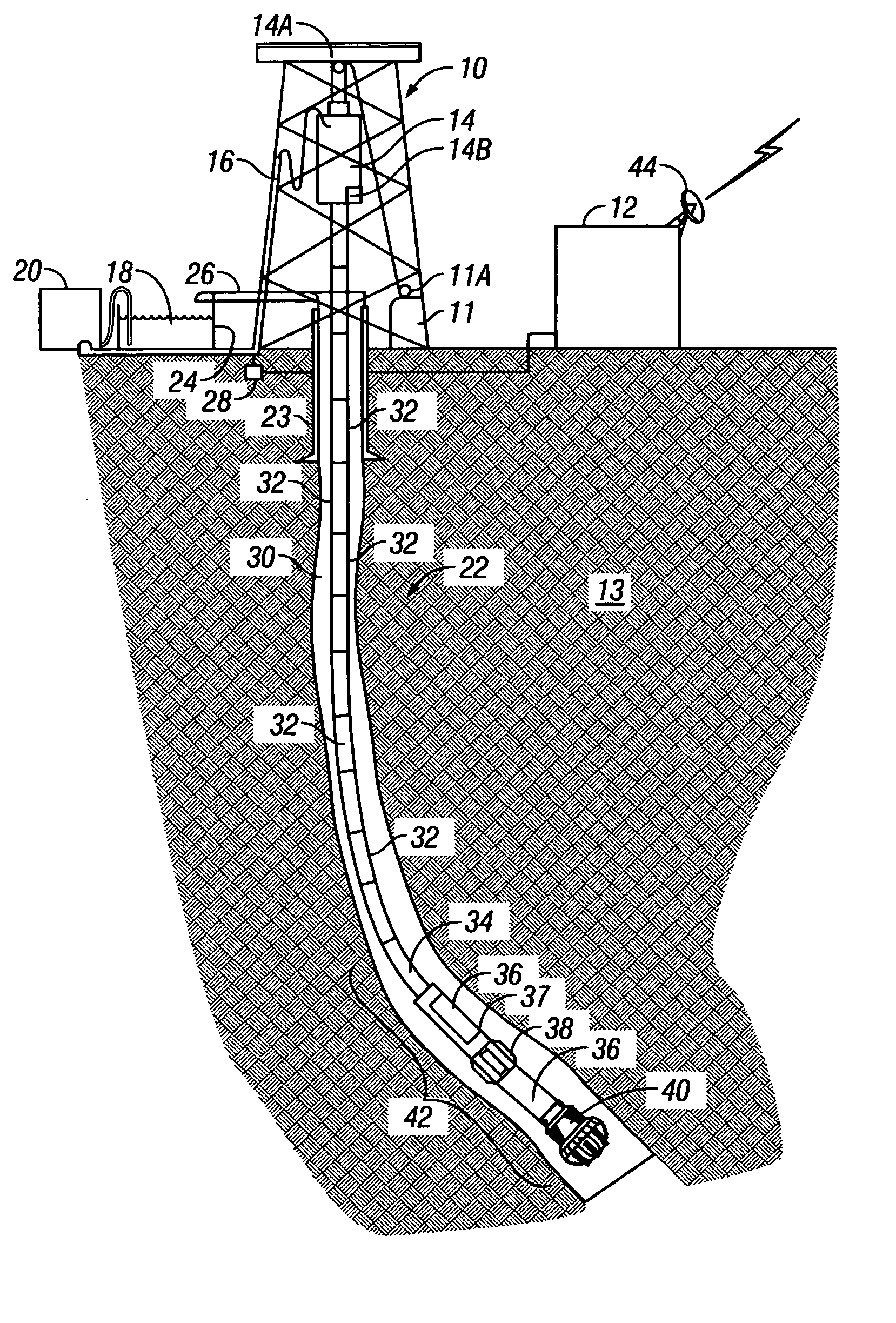
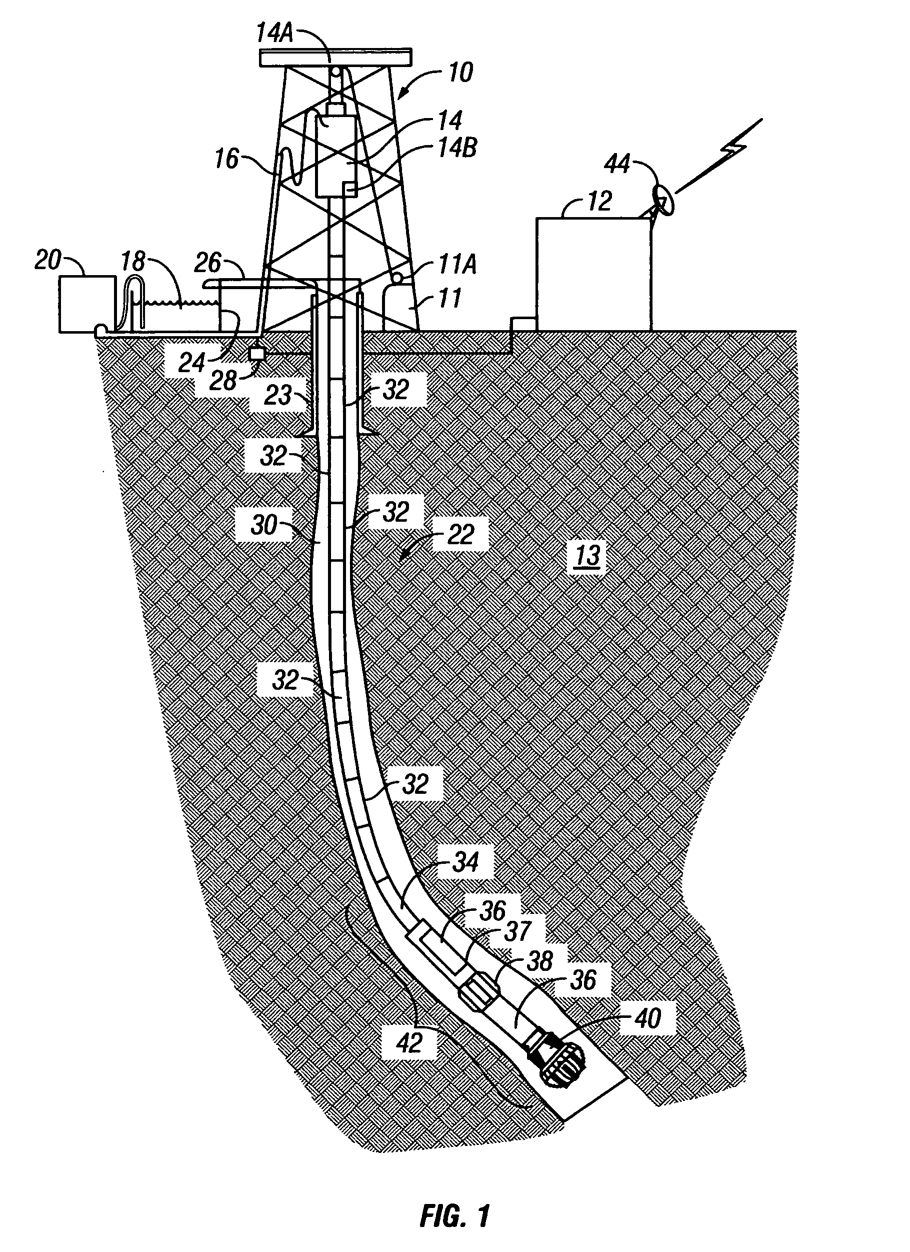
[0029]FIG. 1 shows a typical wellbore drilling operation from which data may be measured and used with various embodiments of the invention. A drilling rig 10 includes a drawworks 11 or similar lifting device known in the art to raise, suspend and lower a drill string. The drawworks 11 for purposes of this description is described collectively and includes a hook, traveling block, wire rope or cable spooled by a winch, and other lifting and control devices well known in the art for lifting and suspending a drill string.

[0030]The drill string includes a number of threadedly coupled sections of drill pipe, shown generally at 32, that extend to the earth's surface at one end. A lowermost part of the drill string is known as a bottom hole assembly (BHA) 42. The BHA 42 includes, in the embodiment of FIG. 1, a drill bit 40 at the lowermost end to cut through earth formations 13 below the earth's surface. The drill bit 40 may be one of many types well known in the art, including roller con...


PUM


Abstract

A method for selecting drilling operating parameters includes characterizing at least one drilling response parameter with respect to lithology. The characterization is performed when a parameter related to drill string dissipative motion parameter below a selected threshold. The at least one drilling response parameter is measured during drilling. Lithology is determined from the measured drilling response parameter. At least one drilling operating parameter is selected to optimize at least one drilling response parameter when a parameter related to drill string dissipative motion falls below a selected threshold for the determined lithology.

Description

CROSS-REFERENCE TO RELATED APPLICATIONS[0001]This is a continuation of International Patent Application No. PCT / US03 / 10175 filed on Apr. 3, 2003. Priority is claimed from U.S. Provisional Application No. 60 / 374,117 filed on Apr. 19, 2002.STATEMENT REGARDING FEDERALLY SPONSORED RESEARCH OR DEVELOPMENT[0002]Not applicable.BACKGROUND OF THE INVENTION[0003]1. Field of the Invention[0004]The invention relates generally to the field of drilling wellbores through the earth. More particularly, the invention relates to methods for determining actual drilling depth of a drill string in a wellbore with respect to time, and application of the actual depth to drilling process control. The invention further relates to methods for characterizing drilling data on the basis of likely quality, and applications for the characterized data.[0005]2. Background Art[0006]Drilling wellbores through the earth includes “rotary” drilling, in which a drilling rig or similar lifting device suspends a drill strin...

Claims


Application Information

Patent Timeline
Patent Type & Authority Patents(United States)
IPC IPC(8): E21B47/12E21B41/00E21B44/00E21B47/04
CPCE21B47/04E21B44/00
Inventor HUTCHINSON, MARK W.
Owner HUTCHINSON MARK W
Why Eureka
Try Eureka