Round undulating blade and blade module for shredder

a technology of which is applied in the field of round undulating blades and blade modules for shredders, can solve the problems of high material cost, inconsistent quality, and increase in cost, and achieve the effect of reducing motor loading and power consumption and reducing power

Inactive Publication Date: 2006-05-16
MICHILIN PROSPERITY
View PDF2 Cites 20 Cited by
  • Summary
  • Abstract
  • Description
  • Claims
  • Application Information

AI Technical Summary

Benefits of technology

[0010]It is a primary objective of the present invention is to provide a round undulating blade for shredders, that is integrally punched from a sheet metal in a die into a round undulating blade to effectively reduce the material cost and the weigh of the blade to thereby reduce the motor loading and power consumption.
[0012]It is another objective of the present invention is to provide a round undulating blade for shredders, that uses the varying curvatures of the round undulating blade to cut paper into paper chips each having a wider center tapering towards the ends, so as to reduce the power that that motor needs to output for cutting the two ends to thereby reduce the motor loading and the power consumption.

Problems solved by technology

However, because the blades are formed by a punch die, the die wear that increases with the time will reduce sharpness of the blade edges, which does not improve until replacing the die, to result in inconsistent quality.
To ensure quality of the blades, it is necessary to shorten the service term of the die, which results in increment of the cost.
Such a limitation attributes to the high material cost, which is less competitive as compared to the current market price.

Method used


Image

  • Round undulating blade and blade module for shredder
  • Round undulating blade and blade module for shredder
  • Round undulating blade and blade module for shredder

Examples


Embodiment Construction

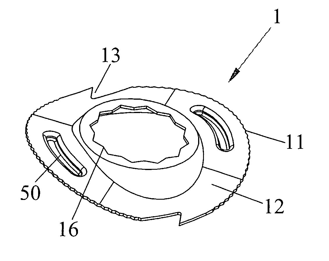
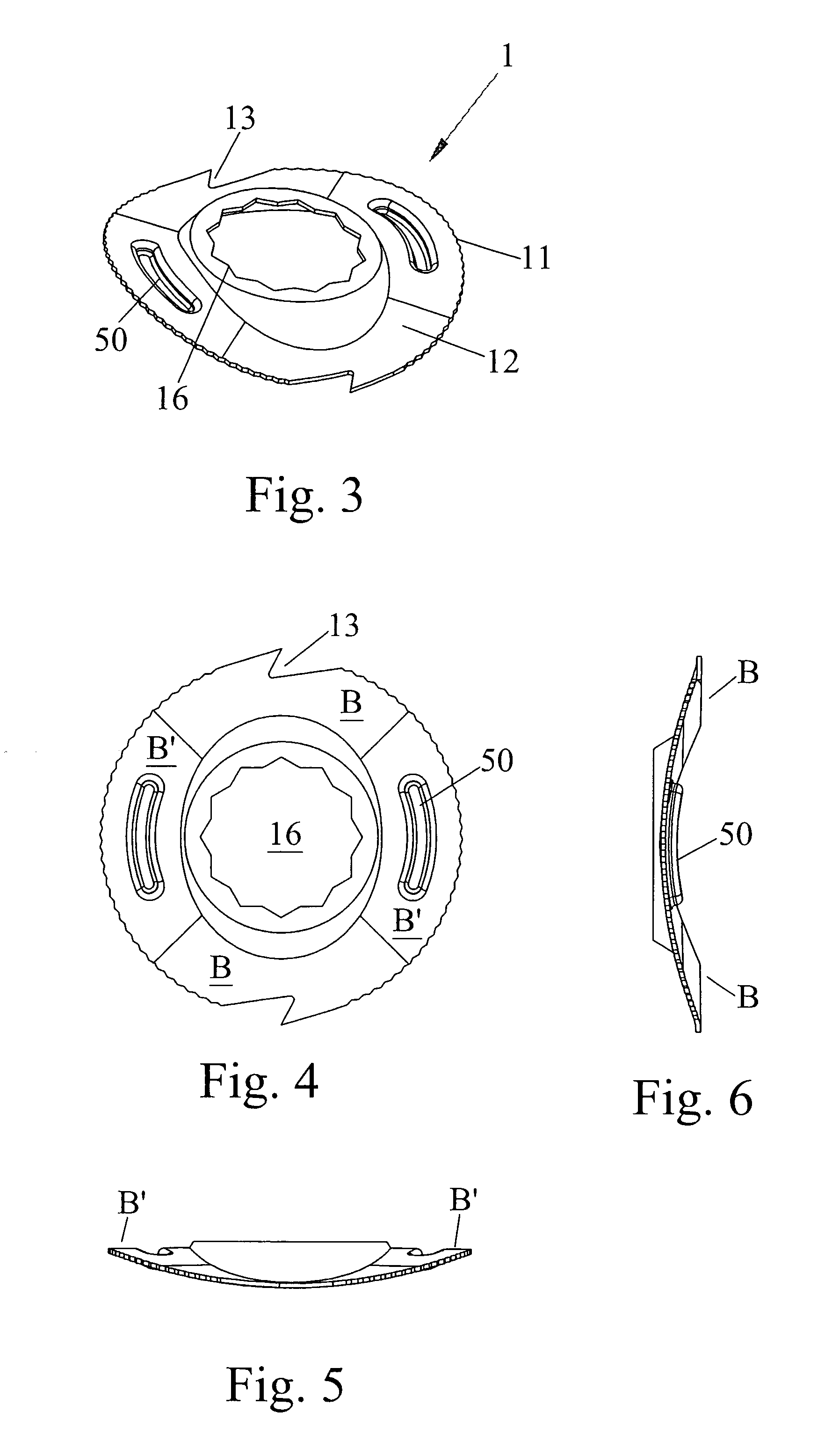
[0041]Please refer to FIGS. 3 to 6, where FIGS. 3 and 4 illustrate the perspective and planar views of the present invention, respectively, and FIGS. 5 and 6 are cross-sectional views taken from lines 5—5 and lines 6—6 in FIG. 4, respectively.

[0042]The above-mentioned views disclose a revolutionized cutting blade 1 for a shredder, which blade is able to provide an optimum sheet capacity based on the various types of shredders. The present invention selects a sheet metal having a minimum thickness of about 0.3 mm as a raw material, the selected sheet metal is punched by a die into a blade including an undulating blade flank 12, formed into two cambers B′ having a first curvature and two cambers B′ having a second curvature alternatively arranged with respect to the cambers B having the first curvature. Preferably, the cambers B, B′ are equally spaced apart from one another. The cambers B, B′ may also be equally spaced apart from each other, if needed. The periphery 11, as shown in FI...


PUM


Abstract

The present invention relates to a round undulating blade for shredder, where a sheet metal is integrally formed into a round undulating blade to serve as the blades for constructing a blade module. The blade includes: a periphery; an undulating blade flank including at least two cambers having a first curvature and at least two cambers having a second curvature alternatively arranged with respect to the cambers having the first curvature; and hooked edges formed on the periphery of the cambers having the first curvature, wherein the undulating blade flank of the blade serves to cut paper along a longitudinal direction to form paper strips having double-tapering end, and the hooked edges serve to cut the strips along a horizontal direction into paper chips. These characteristics help to reduce the manufacturing cost, reduce the motor load and power consumption, to thereby enhance the market competitiveness.

Description

CROSS-REFERENCES TO RELATED APPLICATIONS[0001]Not ApplicableSTATEMENT REGARDING FEDERALLY SPONSORED RESEARCH OR DEVELOPMENT[0002]Not ApplicableDESCRIPTION[0003]1. Field of the Invention[0004]The present invention relates to an improved cutting blade for a shredder, particularly to a round undulating blade that is integrally formed by punching a sheet metal in a punching die or a round undulating blade module that is integrally formed by die-casting.[0005]2. Background of the Invention[0006]The conventional shredders for cutting paper use a plurality of cutting blades and spacers engaging over a rotary cutter shaft, and the shearing force that two parallel and opposite rotary cutter shafts produce for transferring and cutting the paper-to-be-cut along a longitudinal direction into strips. Shredders can be classed into two types, the stripe-cut shredders and crosscut shredders, according to the machine cutting style. The former shredders arrange cutting blades to the rotating cutter s...

Claims


Application Information

Patent Timeline
Patent Type & Authority Patents(United States)
IPC IPC(8): B02C18/16B02C18/18
CPCB02C18/182
Inventor HUNAG, SIMON
Owner MICHILIN PROSPERITY
Why Eureka
Try Eureka